Dilation device and expandable covering for a dilation instrument

a dilation instrument and expandable technology, applied in the field of dilation tool and expandable cover, can solve the problems of inadvertent slippage of the expandable cover, increased trauma risk, etc., and achieve the effects of high elastic stretching, excellent biocompatibility, and simple and cost-effectiv

Active Publication Date: 2018-08-14
KARL STORZ GMBH & CO KG
View PDF21 Cites 0 Cited by
  • Summary
  • Abstract
  • Description
  • Claims
  • Application Information

AI Technical Summary

Benefits of technology

[0005]Moreover, a further object which emerges lies in developing an expandable covering for the expansion section of a dilation instrument, which covering can be coupled quickly and without an aid device to the dilation instrument, and can be produced in a cost-effective manner.
[0033]Moreover, an end sleeve, which is preferably crimped, welded, soldered and / or adhesively bonded to the distal end, is arranged over the distal closed end of the covering. As a result, the covering with the closed end can be produced cost-effectively and quickly from a tube manufactured in an open manner. Here, use can be made of sleeves similar to wire end ferrules known from electrical engineering. Alternatively, the distal end can also be formed from braid and soft solder and a dedicated end ferrule can be dispensed with. If a plastic is used as fabric, it can be heated and formed to make a distal closure.

Problems solved by technology

A simple solution for dilation lies in use of a balloon catheter which is disadvantageous if the balloon bursts and “pumping work” is required by the operator if a gas is used.
Mechanical dilation instruments are often disadvantageous in that comparatively large gaps are formed between the spreading jaws in the spread state, which contributes to an increased risk of trauma due to a pressure load which is too high and due to clamping.
When the dilation mechanism is actuated, the overcoat may inadvertently slip off the expandable end.

Method used


Image

  • Dilation device and expandable covering for a dilation instrument
  • Dilation device and expandable covering for a dilation instrument
  • Dilation device and expandable covering for a dilation instrument

Examples


Embodiment Construction

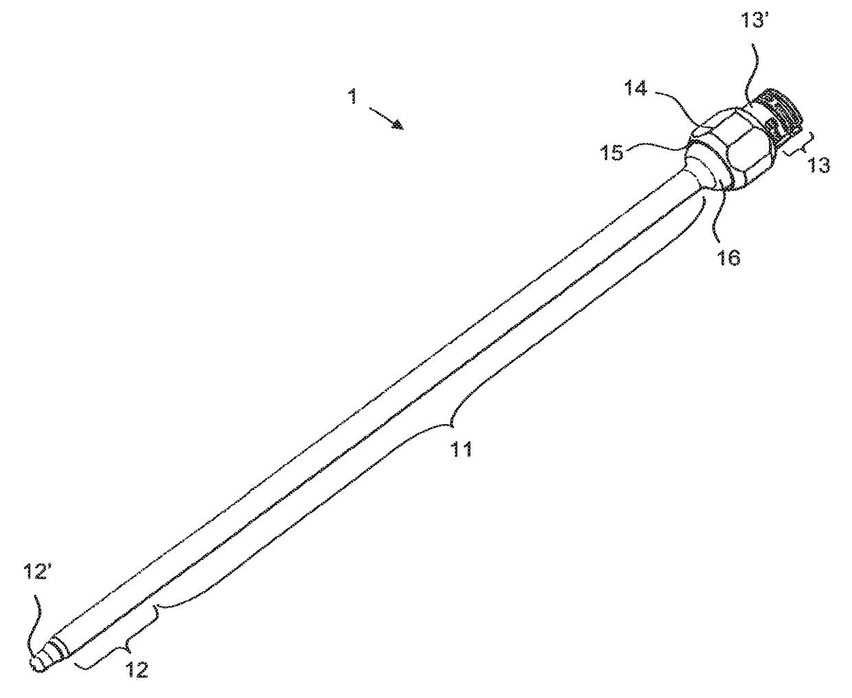
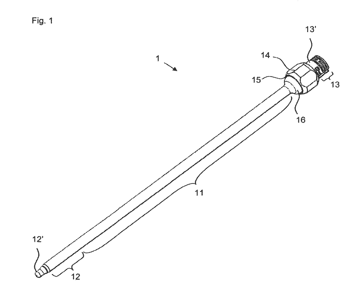
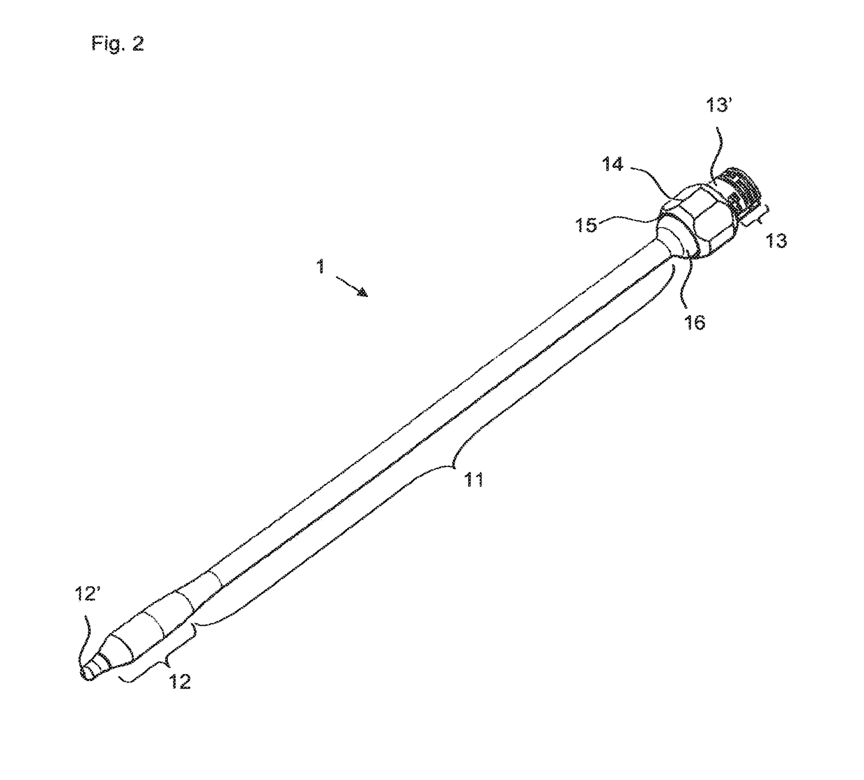
[0054]The covering 1 depicted in FIG. 1 has three sections 11, 12, 13: a proximal coupling section 13, a central shank section 11 and a distal expansion section 12. The covering 1 can be pulled over an elongate dilation tool 3 (see FIG. 10) like a hood; to this end, the covering 1 is open from the coupling section 13 to the tip, i.e. the expansion section 12. In the coupling section 13, the tube of the shank section 11 has been pulled over a coupling sleeve 13′ and adhesively bonded to the latter. The point of adhesion is in turn covered by a grip aid sleeve 14, which is adhesively bonded in a rotationally secured manner to the coupling sleeve 13′ and additionally also held in an interlocking manner by an interaction between a latching recess and a latching lug (see FIG. 6). The tube consists of an elastic mesh material which can be stretched radially by the multiple of the rest diameter thereof without being plastically deformed or even destroyed; this becomes clear at the transiti...


PUM


Abstract

A dilation device including a dilation instrument which includes a distal radially expandable section which is coupled via an elongate shank to a handling section, and an expandable covering with a closed distal end and an open proximal end, for the expansion section of the dilation instrument. The covering has a shank section extending along the shank of the dilation instrument. The open proximal end of the covering is detachably coupled to the distal end of the handling section of the dilation instrument. Furthermore, the covering is disclosed per se, which consists of a mesh material and has a shank section, which is connected to a coupling sleeve at the open proximal end.

Description

FIELD OF THE INVENTION[0001]The present invention relates to a covering for a dilation tool and to a dilation instrument.BACKGROUND OF THE INVENTION[0002]Dilation instruments are used, inter alia, in endoscopic ENT surgery, but also in other specialist areas of medicine. They are used to remove pathological stenoses by virtue of an expandable section being introduced into the region of the stenosis and the section being dilated. A simple solution for dilation lies in use of a balloon catheter which is disadvantageous if the balloon bursts and “pumping work” is required by the operator if a gas is used. If use is made of an incompressible fluid, the biocompatibility thereof, in turn, needs to be taken into account. Purely mechanical dilation instruments are also known; although these usually cannot be dilated in an ideal manner, they do permit sensitive force feedback with fewer hand movements. Mechanical dilation instruments are often disadvantageous in that comparatively large gaps...

Claims


Application Information

Patent Timeline
Patent Type & Authority Patents(United States)
IPC IPC(8): A61M29/00A61B17/24A61B1/32A61B1/00A61B17/00A61B46/17A61B46/10
CPCA61B17/00234A61B1/00112A61B1/32A61B46/10A61B46/17A61B17/24A61M29/00
Inventor BACHER, UWEBLOCHER, MARTINSCHMIDBERGER, JOCHENUNGER, TOBIAS
Owner KARL STORZ GMBH & CO KG
Why Eureka
Try Eureka