Mechanical seal

a mechanical seal and sealing face technology, applied in the direction of engine seals, mechanical apparatus, engine components, etc., can solve the problems of deteriorating sealing performance of sealing faces, leaking of sealed fluid, and sealing noise in the surrounding area, so as to improve the lubricated condition of respective sealing faces, improve sealing effect, and increase the volume of sealed fluid

Active Publication Date: 2018-08-21
EAGLE INDS
View PDF28 Cites 18 Cited by
  • Summary
  • Abstract
  • Description
  • Claims
  • Application Information

AI Technical Summary

Benefits of technology

[0021](1) Even in a case where the sealed fluid is, for example, a fluid of a mixture of a lubricative liquid such as oil in the form of mist exists and a liquid, the lubricative liquid in the form of mist is attached to or condensed in the opening portion of the fluid introduction groove to be supplied by the gravity of the lubricative liquid and by a pressure difference between the opening portion and the end portion to the clearance between the respective sealing faces of the rotating sealing ring and the stationary sealing ring that face each other; therefore, a lubricated condition of the respective sealing faces can be improved.
[0022](2) The fluid circulation groove is provided in the sealing face and the fluid introduction groove is provided at least in the inlet portion of the fluid circulation groove, therefore increasing the volume of the sealed fluid to be introduced to the sealing face. Thus, even in a case where the sealed fluid is, for example, a fluid of a mixture of a gas in which a lubricative liquid such as oil in the form of mist exists and a liquid, the lubricated condition of the respective sealing faces S can be further improved.
[0023](3) In the mechanical seal where the lubricity is improved by the positive pressure generation mechanism and a sealing effect is improved by the pressure release groove, the fluid introduction groove is provided in the radial groove, therefore increasing the volume of the sealed fluid to be introduced to the sealing face. Thus, even in a case where the sealed fluid is, for example, a fluid of a mixture of a gas in which a lubricative liquid such as oil in the form of mist exists and a liquid, the lubricated condition of the respective sealing faces can be further improved.
[0024](4) The fluid likely to flow toward the low-pressure side due to the positive pressure (dynamic pressure) generated in the positive pressure generation mechanism at the high-pressure side is discharged to the high-pressure side; thereby, the sealing effect on the sealing face can be increased.
[0025](5) In the mechanical seal where the lubricity is improved by the positive pressure generation mechanism and the sealing effect is improved by a spiral groove or the pressure release groove, the fluid introduction groove is provided in the radial groove that is inclined so that the sealed fluid may easily flow in and out, therefore further increasing the volume of the sealed fluid to be introduced to the sealing face. Thus, even in a case where the sealed fluid is, for example, a fluid of a mixture of a gas in which a lubricative liquid such as oil in the form of mist exists and a liquid, the lubricated condition of the respective sealing faces can be further improved.

Problems solved by technology

A conventional mechanical seal device may have various problems caused by a sealed fluid when the mechanical seal device seals a clearance between rotating components of an apparatus which uses a chemical fluid, in particular, a refrigerant oil, a cooling medium, or the like.
For example, in a case where a sealed fluid (working fluid) existing around a rotating shaft of a supply device (pump), a chemical device, or the like which supplies a refrigerant oil and an ammonia refrigerant is sealed, for example in a car air-conditioner, a refrigerator compression machine, or the like, there have been revealed various problems caused by a sealed fluid, such as a lack of a lubrication action on a sealing face of a mechanical seal.
In addition, a squeaking phenomenon between the sealing faces of the mechanical seal makes uncomfortable noises to the surrounding area.
Furthermore, sealing performance of the sealing faces is deteriorated by the heat generated between the sliding sealing faces and therefore the sealed fluid may leak.
Likewise, the sealing rings may be worn by the sealed fluid to be damaged thereby.

Method used


Image

  • Mechanical seal
  • Mechanical seal
  • Mechanical seal

Examples


first embodiment

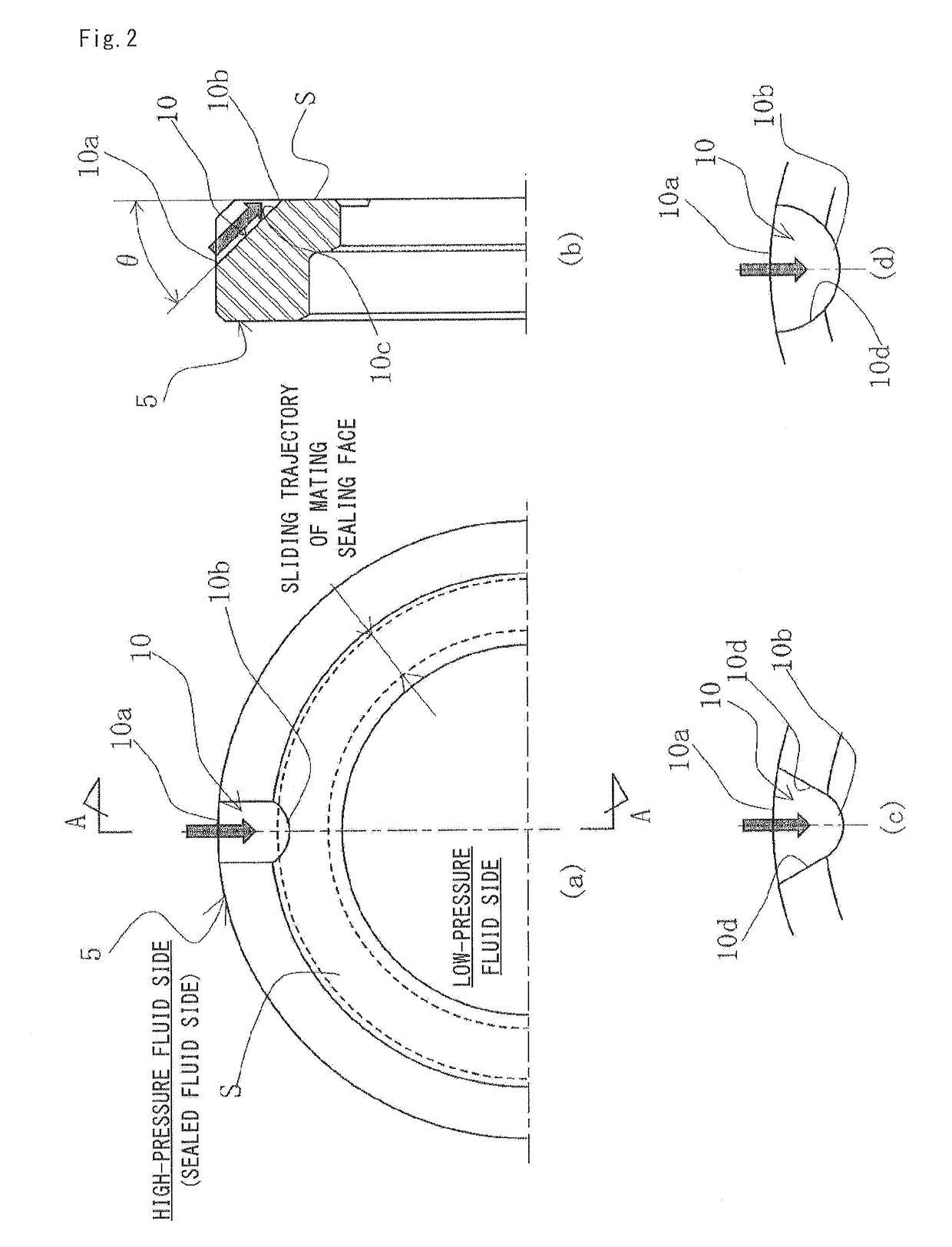
[0034]A mechanical seal according to a first embodiment of the Present invention will be described with reference to FIG. 1 and FIG. 2.

[0035]In addition, radially outward and inward sides of a sealing ring configuring the mechanical seal are respectively described as a high-pressure fluid side (sealed fluid side) and a low-pressure fluid side (atmosphere side) in the present embodiment; however, the present invention is not limited thereto. The high-pressure fluid side and the low-pressure fluid side may be reversely arranged.

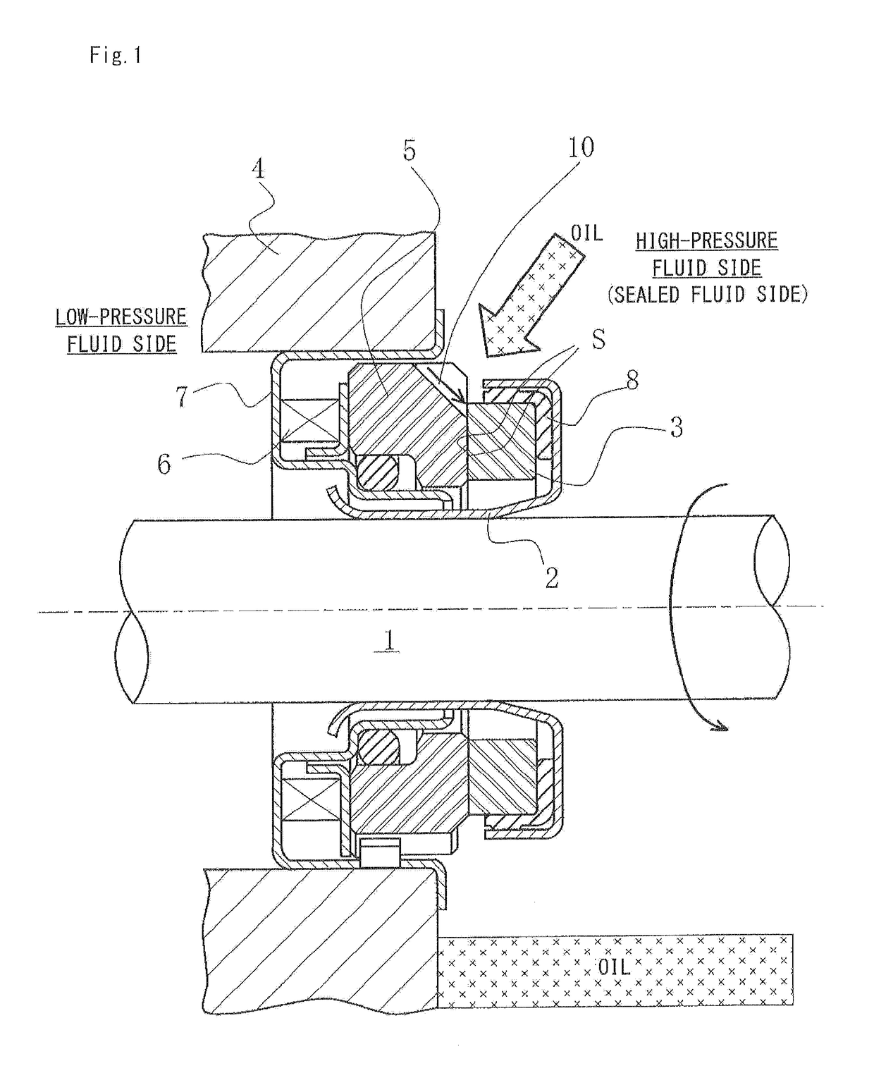
[0036]FIG. 1 is a vertical cross-sectional view illustrating an example of the mechanical seal. The mechanical seal is configured as an inside mechanical seal for sealing a sealed fluid at the high-pressure fluid side, which is likely to leak in a direction from the radially outward side to the radially inward side of a sealing face S (in the present specification, in a case where the sealing face S means respective sealing faces corresponding to a pair of seal...

second embodiment

[0051]The mechanical seal according to a second embodiment of the present invention will be described with reference to FIG. 3.

[0052]In addition, the same reference numbers as those of FIG. 1 and FIG. 2 indicate the same members in FIG. 3 and the descriptions overlapped with the first embodiment will be omitted.

[0053]In FIG. 3, a fluid circulation groove 12 communicated with the high-pressure fluid side and separated from the low-pressure fluid side by a smoothing portion R of the sealing face (the smoothing portion may be referred to as “a land portion” in the present invention) is provided in the sealing face S of the stationary sealing ring 5.

[0054]The fluid circulation groove 12 is configured by an inlet portion 12a through which the fluid flows in from the high-pressure fluid side, an outlet portion 12c through which the fluid flows out to the high-pressure fluid side, and a communication portion 12b which allows a pair of the inlet portion 12a and the outlet portion 12c to com...

third embodiment

[0060]The mechanical seal according to a third embodiment of the present invention will be described with reference to FIG. 4 and FIG. 5.

[0061]In addition, the same reference numbers as those of FIG. 1 and FIG. 2 indicate the same members in FIG. 4 and FIG. 5 and the descriptions overlapped with the first embodiment will be omitted.

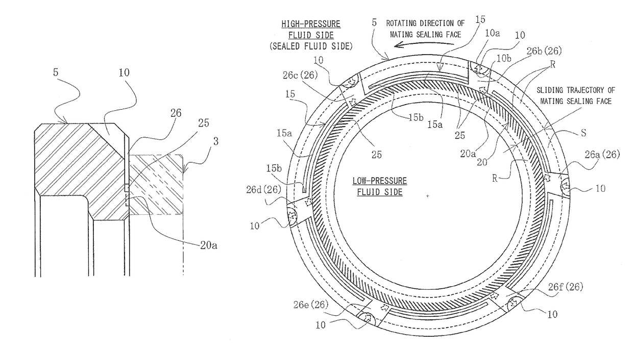
[0062]In FIG. 4, a positive pressure generation mechanism 15, for example, a Rayleigh step mechanism which includes a groove 15a and a Rayleigh step 15b is provided on the sealing face S of the stationary sealing ring 5 at the high-pressure fluid side. The positive pressure generation mechanism 15 generates a positive pressure in accordance with relative rotation and sliding between the stationary sealing ring 5 and the rotating sealing ring 3. The positive pressure generation mechanism 15 is separated from the high-pressure fluid side and the low-pressure fluid side by the land portion R (corresponding to the smoothing portion of the sealing face S), and...


PUM


Abstract

Provided is a mechanical seal includes a fluid introduction groove provided in a sealing face of a stationary sealing ring and having an opening portion which is opened to the sealed fluid and an end portion which is provided opposite to the opening portion. The end portion being located between respective sealing faces S, the fluid introduction groove introducing the sealed fluid from the opening portion to a clearance between the respective sealing faces S. The fluid introduction groove is provided to be inclined at an acute angle to the sealing face S of the stationary sealing ring in a direction from the end portion to the opening portion.

Description

TECHNICAL FIELD[0001]The present invention relates to a mechanical seal used in automobiles, general industrial machineries, and other fields requiring seals, and particularly to a contact type mechanical seal for sealing a fluid of a mixture of a liquid intended for use in compression machines, pumps, or the like and a gas.BACKGROUND ART[0002]A conventional mechanical seal device may have various problems caused by a sealed fluid when the mechanical seal device seals a clearance between rotating components of an apparatus which uses a chemical fluid, in particular, a refrigerant oil, a cooling medium, or the like. For example, in a case where a sealed fluid (working fluid) existing around a rotating shaft of a supply device (pump), a chemical device, or the like which supplies a refrigerant oil and an ammonia refrigerant is sealed, for example in a car air-conditioner, a refrigerator compression machine, or the like, there have been revealed various problems caused by a sealed flui...

Claims


Application Information

Patent Timeline
Patent Type & Authority Patents(United States)
IPC IPC(8): F16J15/34
CPCF16J15/3412F16J15/3416F16J15/342F16J15/34
Inventor KATORI, HIKARUCHIBA, KEIICHIITADANI, MASATOSHI
Owner EAGLE INDS
Why Eureka
Try Eureka