Apparatus and method for transferring electronic devices

a technology of electronic devices and apparatuses, applied in the direction of conveyor parts, transportation and packaging, instruments, etc., can solve the problems of increasing the risk of falling, affecting the efficiency of the apparatus, and affecting the safety of the equipment, so as to improve the efficiency and productivity of the apparatus, and simplify the adjusting mechanism

Active Publication Date: 2018-08-21
ASMPT SINGAPORE PTE LTD
View PDF6 Cites 4 Cited by
  • Summary
  • Abstract
  • Description
  • Claims
  • Application Information

AI Technical Summary

Benefits of technology

[0013]With the above-mentioned apparatus, the offsets between the respective pairs of holders and handlers can be compensated by the adjustments. This allows the electronic devices to be more securely retrieved by the holders, hence reducing the chances of dropping and damaging the devices. Thus, the apparatus can be reliably used for transferring electronic devices including those which are very small in size. Further, since offsets between the pick heads can be compensated by the adjusting mechanism, the demand on part fabrication and alignment is less stringent, and precision machine parts are not required. The use of the adjusting mechanism also eliminates the need for manual adjustments of the pick heads after the pick heads have been changed. This helps to reduce the machine down time and improve machine throughput.
[0026]The expected handler stopping position may be located away from the expected holder stopping position. This provides more flexibility in the placement of the cameras.

Problems solved by technology

Although the prior art methods described above are able to flip the electronic devices, they involve multiple transfers of the electronic devices and this can lead to potential problems.
One problem arising from this is that each time the electronic device is transferred, there is a chance that the electronic device is not situated in the center of the pick head 108, 114 where the suction hole is.
This increases the risk of dropping and hence, damaging the electronic device.
This risk is higher when handling smaller electronic devices if the pick heads 108, 114 have suction holes that are so small that a slight offset of the electronic devices from their centers will cause the suction holes to be severely misaligned with respect to the devices.
A further problem with the apparatus 100 is that the distance between the center of the first main body 106 and each of the first pick heads 108 may vary.
This is due to fabrication errors and errors introduced when the pick heads are changed (such changes are performed so as to handle different devices e.g. devices having different sizes and characteristics).
Therefore, there is a chance that some of the first pick heads 108 may not centrally retrieve the electronic devices.
As a result, the electronic device may drop.
However, such adjustments require highly skilled workers and are extremely time consuming.
Moreover, the chances of dropping an electronic device increase as the size of the electronic device decreases.
Thus, it is especially risky for the apparatus 100 to handle very small electronic devices, in particular, those with a pick-up surface area of 0.6 mm×0.3 mm or less.

Method used


Image

  • Apparatus and method for transferring electronic devices
  • Apparatus and method for transferring electronic devices
  • Apparatus and method for transferring electronic devices

Examples


first embodiment

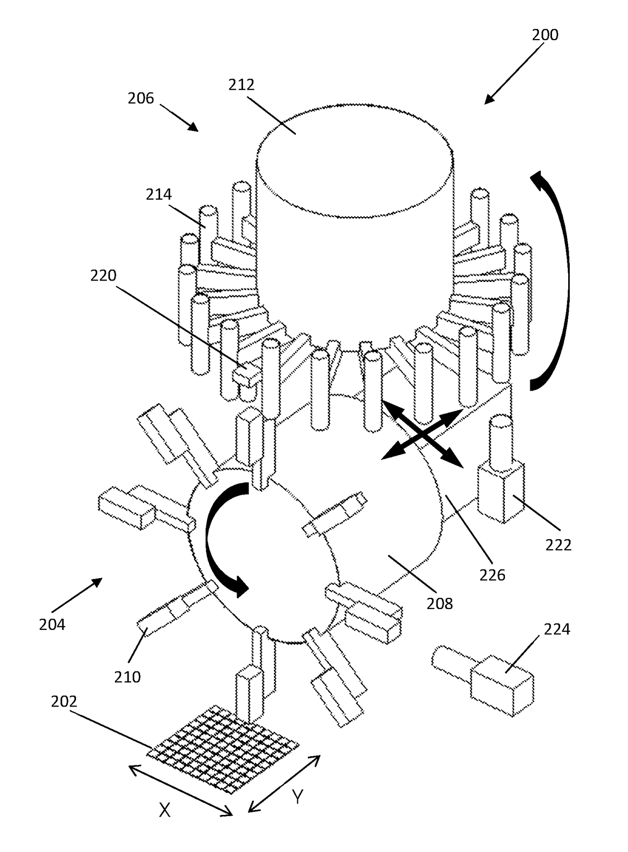
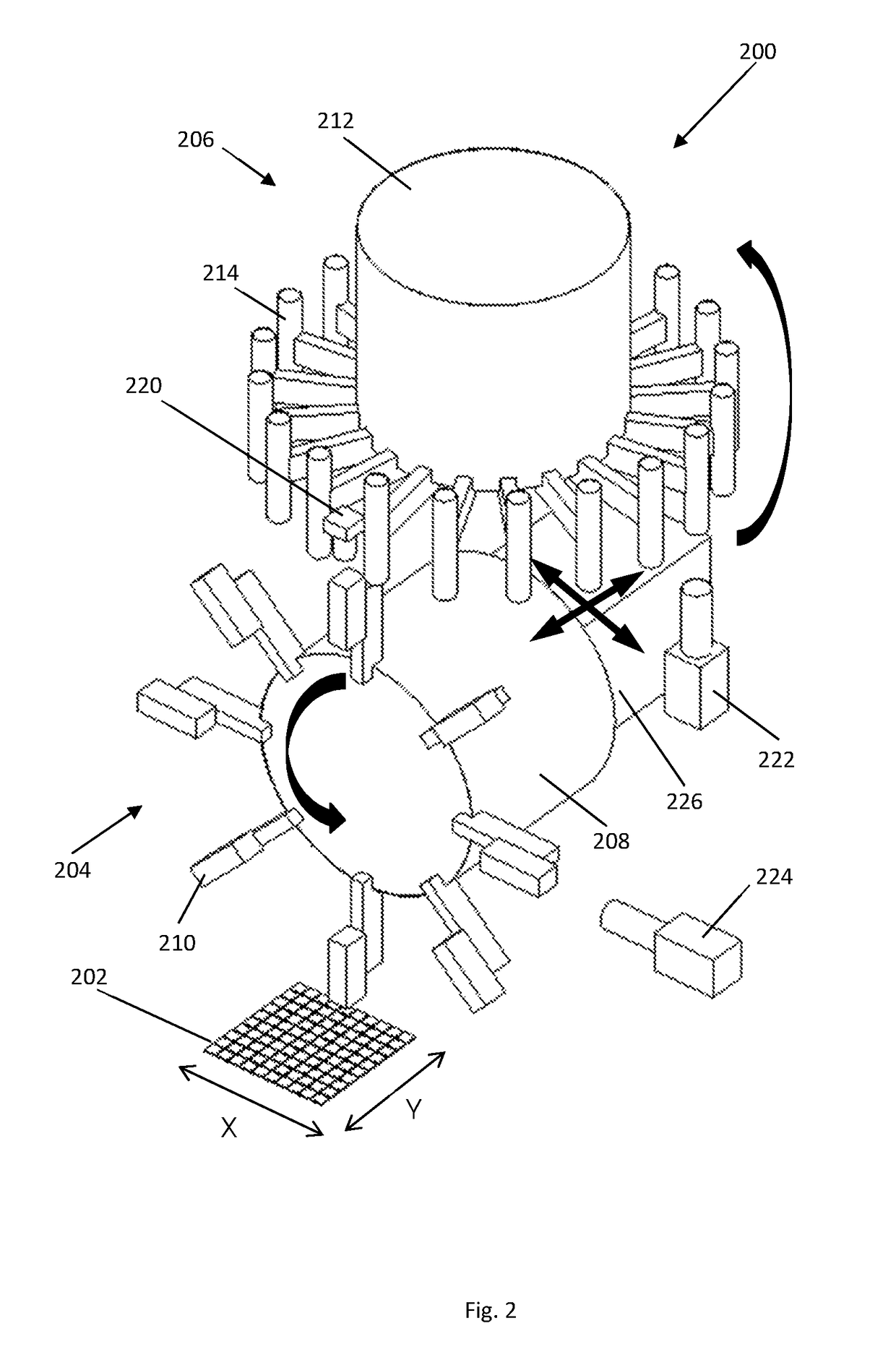
[0037]FIG. 2 shows a perspective view of an apparatus 200 for transferring electronic devices from a holding unit in the form of a receiving plate 202 to a processing station (not shown in FIG. 2) according to the present invention.

[0038]As shown in FIG. 2, the apparatus 200 comprises a first rotating mechanism in the form of a vertically rotating flipper 204 and a second rotating mechanism in the form of a horizontally rotating main turret 206.

[0039]The flipper 204 includes a cylindrical flipper body 208 and a plurality of handlers in the form of flipper pick heads 210. The flipper pick heads 210 are located at one end of the flipper body 208 and are distributed, spaced apart from one another, around a circumference of the flipper body 208. Similarly, the main turret 206 includes a cylindrical turret body 212 and a plurality of holders in the form of turret pick heads 214. The turret pick heads 214 are also located at one end of the turret body 212 around the circumference of the t...

second embodiment

[0064]FIG. 7 shows a perspective view of an apparatus 700 for transferring electronic devices from a holding unit in the form of a receiving plate 202′ to a processing station (not shown) according to the present invention. The apparatus 700 is similar to the apparatus 200 and thus, the same parts will have the same reference numerals with the addition of prime.

[0065]As shown in FIG. 7, the apparatus 700 also comprises a vertically rotating flipper 204′, a horizontally rotating main turret 206′, a down-look camera 220′, an up-look camera 222′ and a side-look camera 224′. The apparatus 700 also includes a computing unit and a storage device similar to that of the apparatus 200.

[0066]However, the adjusting mechanism of the apparatus 700 is in the form of a single axis driving mechanism 702, instead of the X / Y driving mechanism 226 as in the apparatus 200. In particular, this single axis driving mechanism 702 comprises a casing which holds a motor that is operable to move shafts connec...


PUM


Abstract

The present invention relates to an apparatus for transferring electronic devices from a holding unit to a processing station. The apparatus comprises first and second rotating mechanisms having a plurality of handlers and a plurality of holders respectively, an imaging mechanism, a processor and an adjusting mechanism. In use, a handler retrieves an electronic device from the holding unit and moves the device to a transfer position. A holder retrieves the electronic device from the handler at the transfer position and transfers the electronic device to the processing station. Prior to this retrieval, the adjusting mechanism adjusts a relative position between the holder and the handler at the transfer position. This adjustment is based on offsets calculated by the processor using images of the handler and holder captured by the imaging mechanism. The adjustment allows the electronic device to be retrieved more securely by the holder.

Description

FIELD OF THE INVENTION[0001]The present invention relates to an apparatus and method for transferring electronic devices from a holding unit (for example, a receiving plate) to a processing station.BACKGROUND OF THE INVENTION[0002]Diced electronic devices are usually mounted on a receiving plate in such a way that their leads or electrical contact points face away from the plate. After picking up these devices from the receiving plate, the devices often have to be flipped so that subsequent processes such as functional testing or visual integrity checking can be performed on them.[0003]Prior art methods have been developed to flip electronic devices before transferring them to processing stations for subsequent processes.[0004]For example, U.S. Pat. No. 6,171,049 describes using an intermediate station for flipping a work-piece. In particular, a first head of a transfer unit is used to pick up the work-piece from the receiving plate and subsequently, the work-piece is brought to the...

Claims


Application Information

Patent Timeline
Patent Type & Authority Patents(United States)
IPC IPC(8): G06F7/00H05K3/30H01L21/677
CPCH01L21/67706H01L21/67736H01L21/67721H05K13/0404H05K13/043H05K13/08H01L21/67144H01L24/75H01L2224/7565H05K13/0812H05K13/0413
Inventor CHENG, CHI WAHLAU, KAI FUNG
Owner ASMPT SINGAPORE PTE LTD
Why Eureka
Try Eureka