Rotary electric machine for a vehicle

a technology of electric machines and vehicles, applied in the direction of electric motor control, electrical apparatus, control systems, etc., can solve the problems of parasitic diodes, inability to detect the disconnection of power ground terminals, and inability to protect elements connected to power ground terminals, so as to achieve the effect of reliably preventing current from flowing

Active Publication Date: 2018-08-21
DENSO CORP
View PDF58 Cites 1 Cited by
  • Summary
  • Abstract
  • Description
  • Claims
  • Application Information

AI Technical Summary

Benefits of technology

[0011]An embodiment provides a rotary electric machine for a vehicle which can reliably prevent current from flowing from a power system circuit to a control system circuit.
[0013]An embodiment provides a rotary electric machine for a vehicle which can protect an element connected to a power ground terminal.
[0014]An embodiment provides a rotary electric machine for a vehicle which can detect disconnection of a control ground terminal by a simple configuration.

Problems solved by technology

However, even if the protection circuit of JP-A-7-84655 is applied to the power transistor, which is included in a power converter of the rotary electric machine for a vehicle, current flows through a parasitic diode when the power transistor is turned off.
However, the function of the electronic circuit of Japanese Patent No. 2504586 cannot be applied to a case where one ground terminal is provided for the whole electronic circuit, and a plurality of ground terminals are individually grounded, and when one of the ground terminals is disconnected.
For example, when assuming that a power ground terminal, which is connected to a power converter forming an inverter of a rotary electric machine for a vehicle, and a control ground terminal, which is connected to a controller controlling the power converter, are individually grounded, and the power ground terminal is disconnected, disconnection of the power ground terminal cannot be detected, and elements connected to the power ground terminal cannot be protected.
For example, considering that disconnection of a control ground terminal is detected which grounds a control system circuit of the rotary electric machine for a vehicle, it is difficult to provide a current sensor for detecting the disconnection of the control ground terminal (open fault) because the space for installing the rotary electric machine is limited due to the requirement for miniaturization.
In addition, since the amount of current flowing to the control system circuit is relatively small, it is difficult to accurately determine disconnection of the ground terminal based on the relationship between the current and the voltage.

Method used


Image

  • Rotary electric machine for a vehicle
  • Rotary electric machine for a vehicle
  • Rotary electric machine for a vehicle

Examples


first embodiment

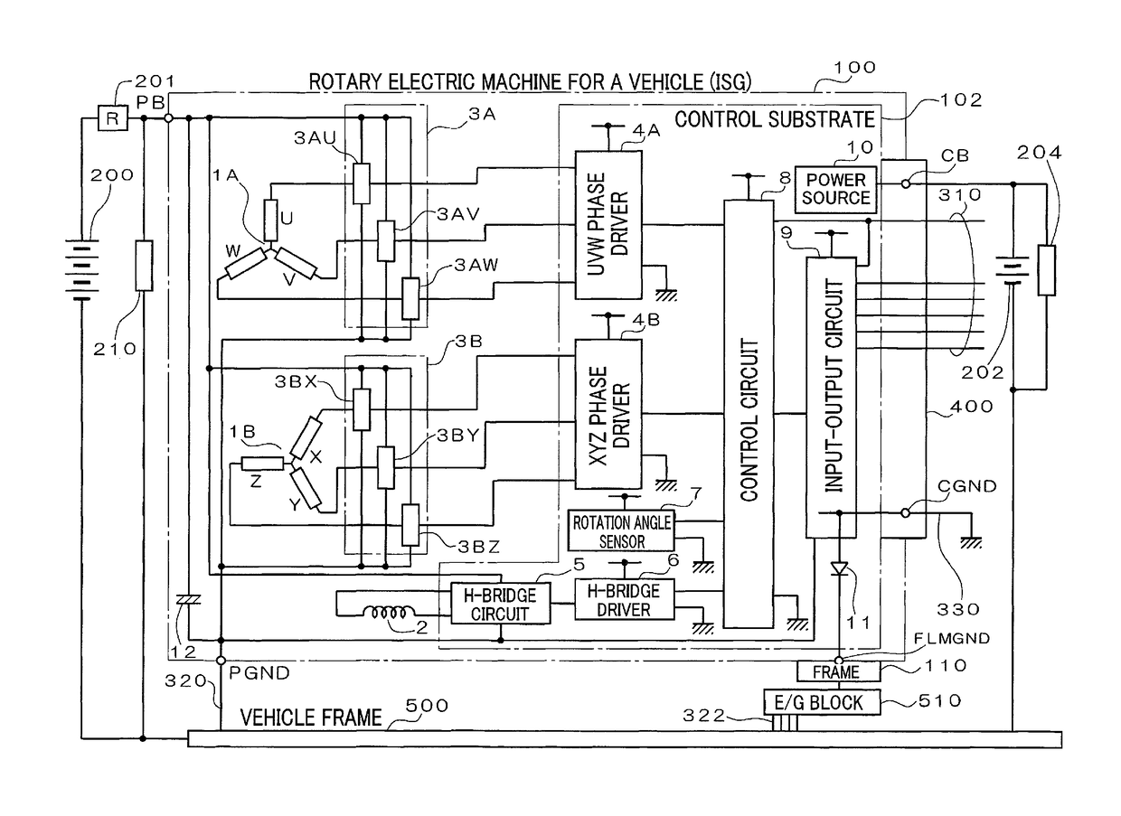
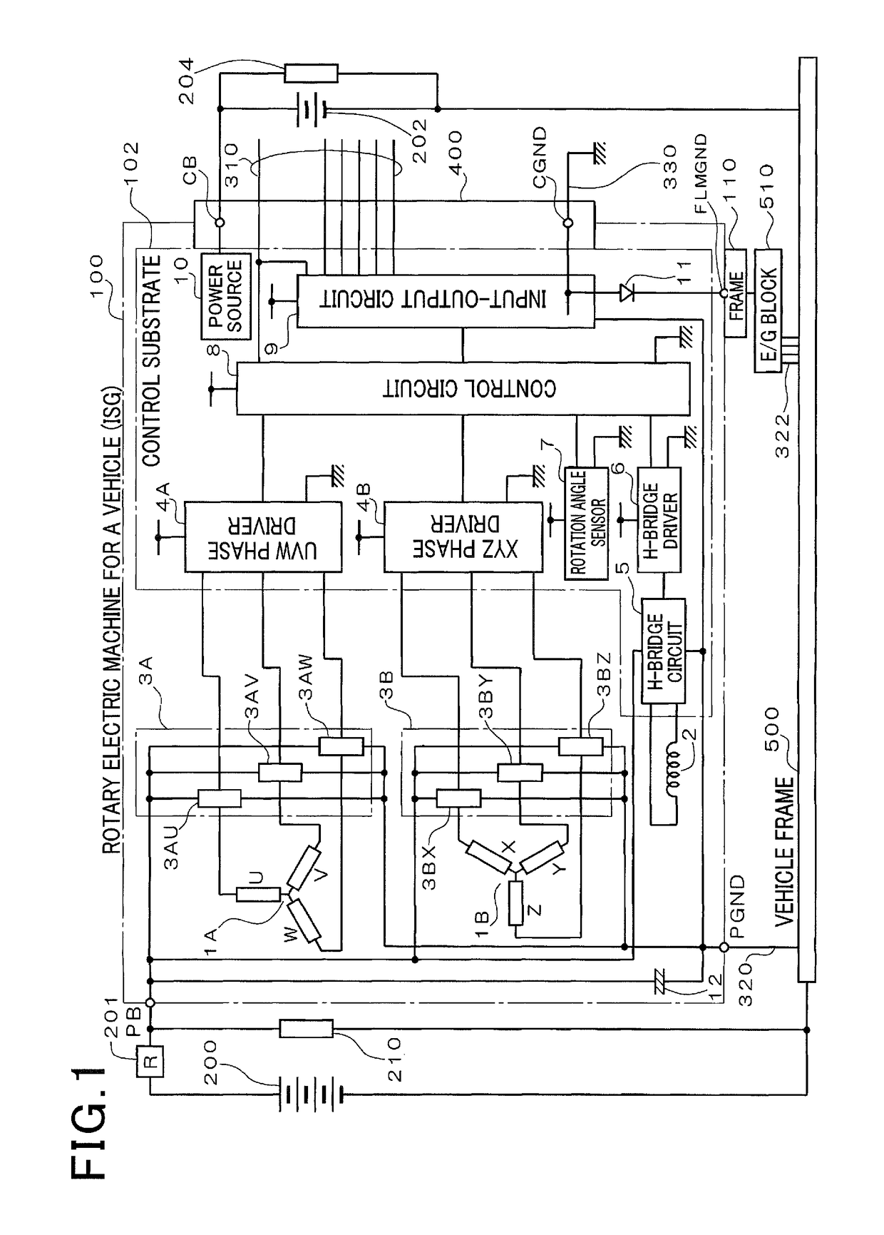
[0028]As shown in FIG. 1, a rotary electric machine 100 for a vehicle includes two stator windings 1A, 1B, a field winding 2, two MOS module groups 3A, 3B, a UVW phase driver 4A, an XYZ phase driver 4B, an H-bridge circuit 5, an H-bridge driver 6, a rotation angle sensor 7, a control circuit 8, an input-output circuit 9, a power circuit 10, a diode 11, and a capacitor 12. The rotary electric machine 100 is referred to as an ISG (integrated starter generator), and has a function of an electric motor and a function of a generator.

[0029]The stator winding 1A is a three-phase winding including a U-phase winding, a V-phase winding, and a W-phase winding, and is wound around a stator core (not shown). Similarly, the stator winding 1B is a three-phase winding including an X-phase winding, a Y-phase winding, and a Z-phase winding, and is wound around the stator core and at a position displaced 30 electrical degrees with respect to the stator winding 1A. In the present embodiment, the two st...

second embodiment

[0085]The rotary electric machine 100 of the second embodiment has the same configuration as that of the rotary electric machine 100 described in the first embodiment.

[0086]Hereinafter, detection operation and protection operation are described which are performed when the ground harness 320 connected to the power ground terminal PGND is disconnected.

[0087]In the present embodiment, the potential of the power ground terminal PGND is monitored with reference to the potential of the control ground terminal CGND. If the potential difference between the power ground terminal PGND and the control ground terminal CGND exceeds a first voltage range, the disconnection of the ground harness 320 is detected.

[0088]Note that the “disconnection of the ground harness 320” includes a state where the contact resistance becomes higher than an assumed acceptable value due to loosing nuts for connection, in addition to a state where one end of the ground harness 320 is completely separated from the po...

third embodiment

[0115]The rotary electric machine 100 of the second embodiment has the same configuration as that of the rotary electric machine 100 described in the first embodiment.

[0116]According to the rotary electric machine 100 for a vehicle of the third embodiment, if the control ground terminal CGND grounding control system circuits is disconnected, the potential thereof shifts by the forward voltage of the diode 11. Hence, by monitoring the potential of another portion with reference to the potential of the control ground terminal CGND, the disconnection of the control ground terminal CGND can be detected. Specifically, monitoring the potential of another portion is required, but detecting the current flowing through the control ground terminal CGND is not required. Hence, the disconnection of the control ground terminal CGND can be detected by a simple configuration.

[0117]In addition, a specific portion is the power ground terminal PGND. The CGND disconnection detection section 82 detects...


PUM


Abstract

A rotary electric machine for a vehicle is provided. The rotary electric machine includes a power system circuit which has a power element and is grounded via a first ground terminal and a first connecting line and a control system circuit which controls the power system circuit and is grounded via a second ground terminal and a second connecting line.

Description

CROSS-REFERENCE TO RELATED APPLICATION[0001]This application is based on and claims the benefit of priority from earlier Japanese Patent Applications No. 2013-99019 filed May 9, 2013, No. 2013-99903 filed May 10, 2013, and No. 2013-99904 filed May 10, 2013, the descriptions of which are incorporated herein by reference.BACKGROUND[0002]Technical Field[0003]The present invention relates to a rotary electric machine for a vehicle, the machine being installed in a passenger car, a truck or the like.[0004]Related Art[0005]Conventionally, a drive circuit is known which includes a protection circuit which logically detects overheat and over current of a power transistor to limit the operation thereof (for example, refer to JP-A-7-84655). This protection circuit prohibits the power transistor from being turned on when overheat or over current of the power transistor is detected which drives a load connected to the drive circuit.[0006]According to the configuration of JP-A-7-84655, when an a...

Claims


Application Information

Patent Timeline
Patent Type & Authority Patents(United States)
IPC IPC(8): H02H7/06H02H7/08H02H5/10H02P29/024
CPCH02H7/06H02P29/0243H02H5/105H02H7/08
Inventor HORIHATA, HARUMIASADA, TADATOSHIKOYASU, TAKAHISA
Owner DENSO CORP
Why Eureka
Try Eureka