
Method and system for high-precision two-way fiber-optic time transfer

a fiber optic and time transfer technology, applied in the field of fiber optic time and frequency transfer, can solve the problems of inability to achieve a precision of better than one nanosecond, its stability, and requires relatively simple and low cost equipment, and achieve the effect of maintaining the propagation delay symmetry of the fiber link

Active Publication Date: 2018-08-28
SHANGHAI JIAOTONG UNIV
View PDF16 Cites 0 Cited by
  • Summary
  • Abstract
  • Description
  • Claims
  • Application Information

AI Technical Summary

Benefits of technology

This approach effectively overcomes the limitations of previous methods by maintaining propagation delay symmetry and enhancing precision, reducing the impact of optical fiber backscattering, and achieving stable high-precision two-way time transfer over long distances with reduced complexity and cost.

Problems solved by technology

GPS common view requires relatively simple and low cost equipment, but is unable to achieve a precision of better than one nanosecond.
Two-way satellite time transfer has a precision at the level of sub-nanosecond, but its stability, particularly in short-term, is prone to disturbance by the free space.
So the precision of two-way satellite time transfer is difficult to be further improved, with further disadvantages in the security and high cost.
In order to suppress the influences from Raleigh backscattering and Fresnel reflection on the transmitted timing signals, both of the aforementioned schemes adopt bidirectional WDM transmission method (that is, different transmission optical wavelengths for two directions), and result in a bidirectional propagation delay asymmetry due to the fiber dispersion, which increases with the increase of distance and limits the precision of two-way time transfer over long distance.
As regarding to the round-trip method, it is difficult to accurately calibrate the link delay for thousands of kilometers time transfer, due to the dispersion difference of fiber links in the practical networks.
However, high-precision spread spectrum coding / decoding is complex and has a high cost.

Method used


Image

  • Method and system for high-precision two-way fiber-optic time transfer
  • Method and system for high-precision two-way fiber-optic time transfer
  • Method and system for high-precision two-way fiber-optic time transfer

Examples


Embodiment Construction

[0046]In combination with an embodiment and the drawings hereunder provided, the present invention will be further enunciated. The embodiment is based on the technical solutions of the present invention and is provided with detailed implementation methods and processes, but is not meant to limit the scope of protection of the present invention.

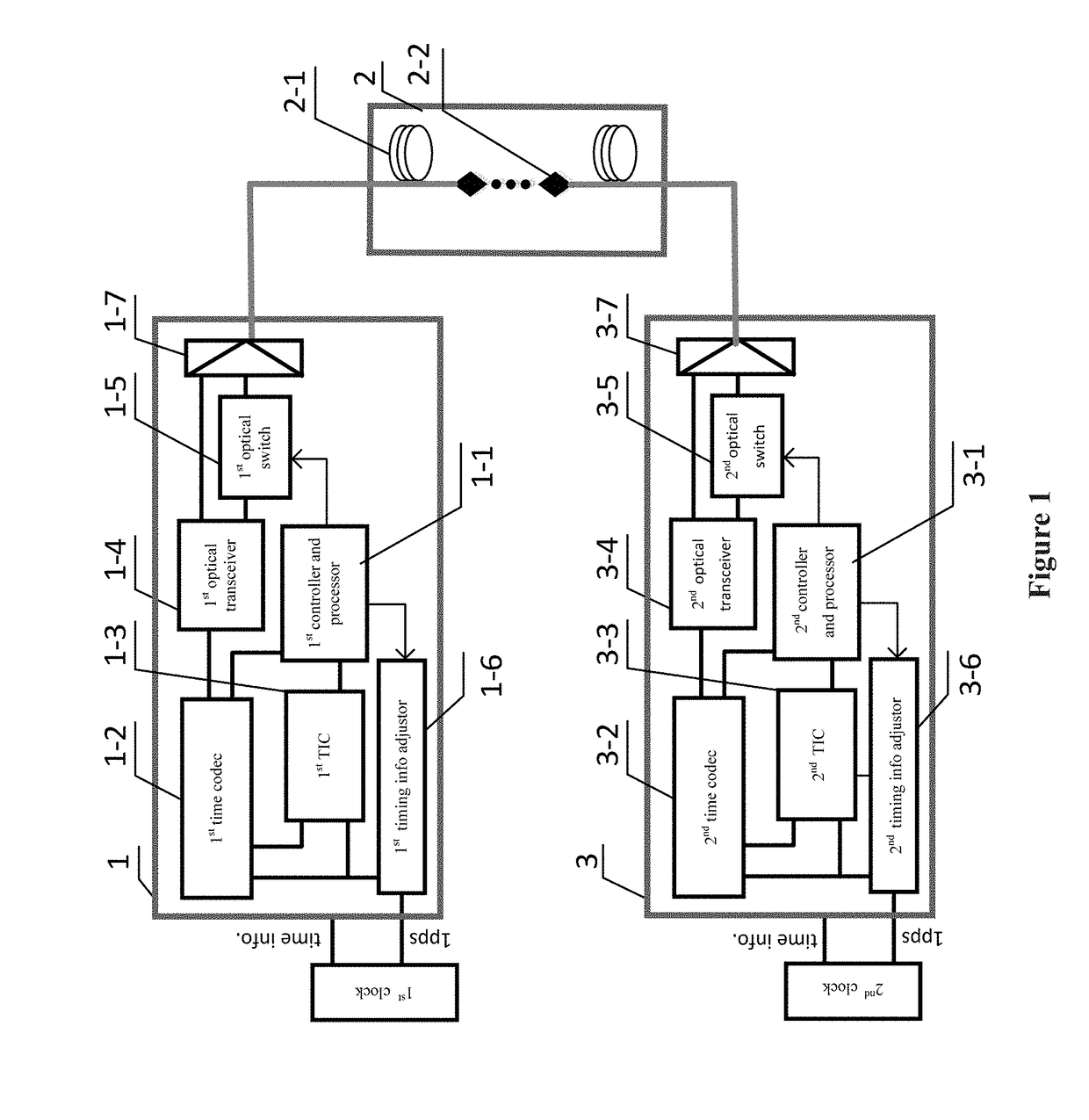
[0047]As shown in FIG. 1, the optical fiber link 2 is constituted by bidirectional optical amplifiers and optical fibers. A first fiber-optic time synchronization unit 1 is on an end of the optical fiber link 2, and a second fiber-optic time synchronization unit 3 is on the other end of the optical fiber link 2.

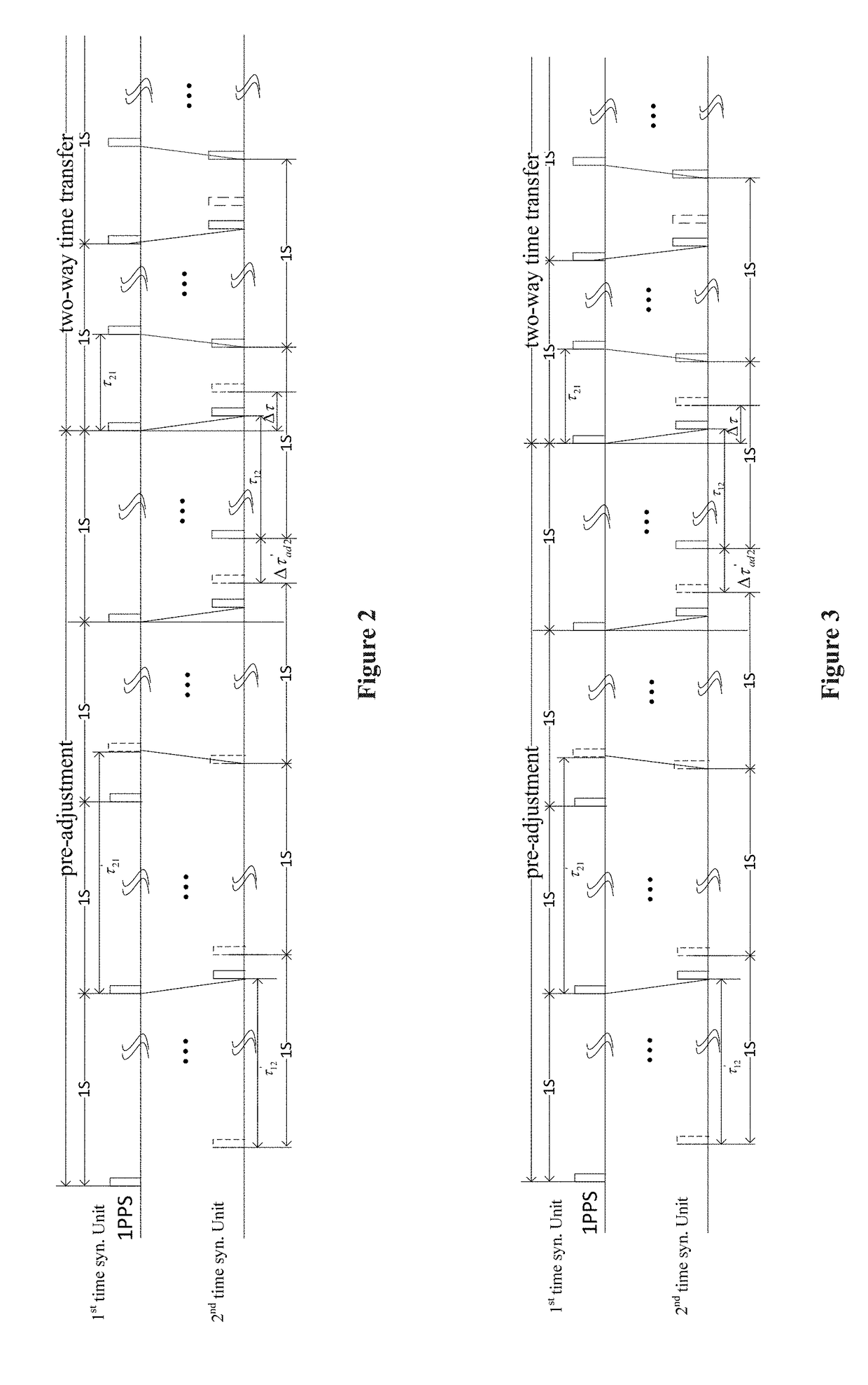
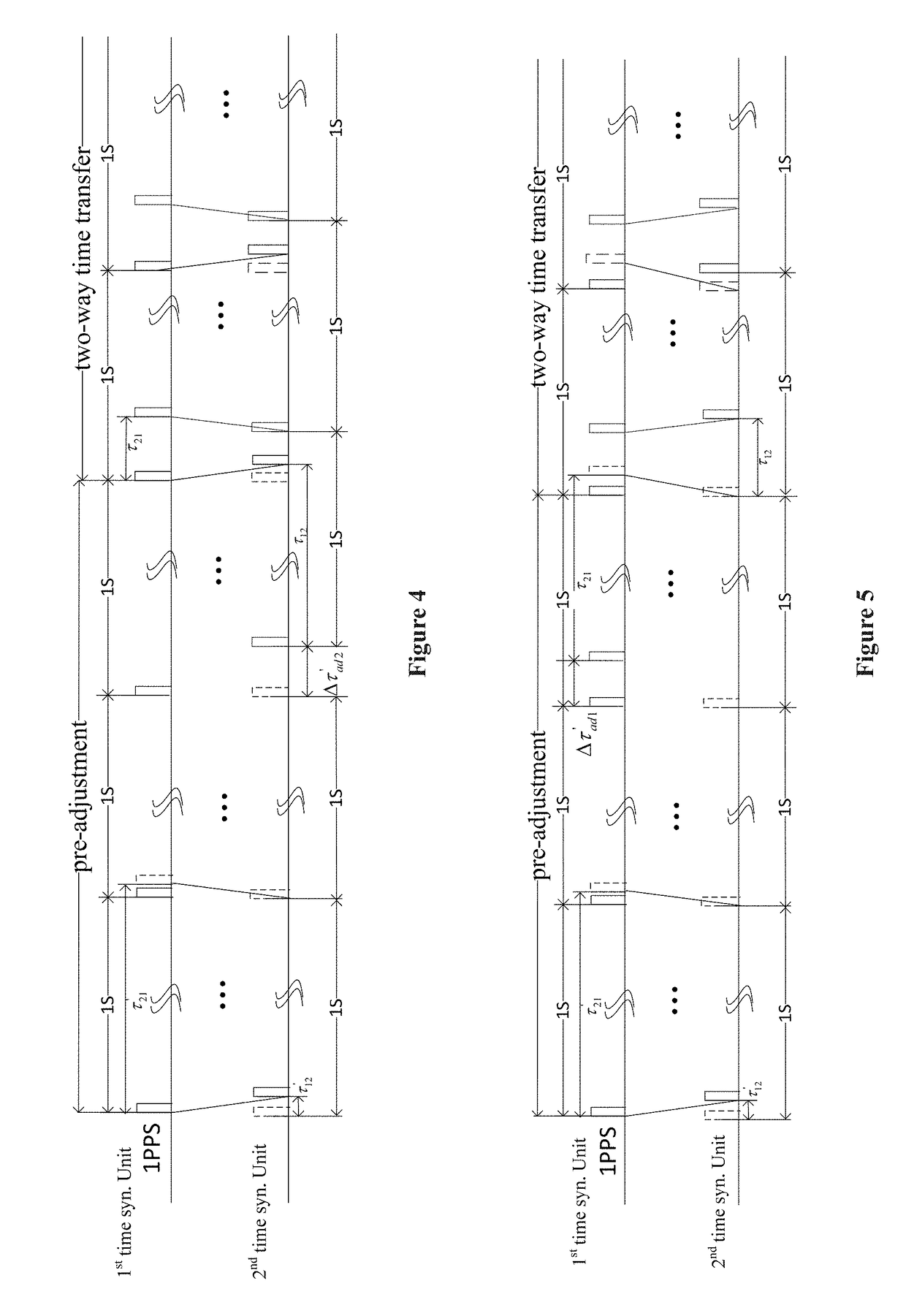
[0048]A first controller and processor 1-1 of the first fiber-optic time synchronization unit, at detecting a timing signal outputted by a first time delay adjustor 1-6, controls a first fiber-optic time codec 1-2 in coding a time code, and switches on a first optical switch 1-5. The coded time code is transformed to an optical signal v...


PUM


Abstract

A method and system for high-precision two-way fiber-optic time transfer comprising pre-adjusting, including calculating a local timing signal adjustment amount for a first fiber-optic time synchronization unit and a second fiber-optic time synchronization unit, and the corresponding adjusting. and following steps including the two fiber-optic time synchronization units conducting two-way time transfer based on a time division multiplexing transmission over an optical fiber link. The present invention realizes high-precision fiber-optic time transfer by combining two-way time transfer and bidirectional time division multiplexing technique.

Description

CROSS-REFERENCE TO RELATED APPLICATIONS[0001]The subject application is a continuation-in-part of PCT / CN2014 / 083164 filed on Jul. 28, 2014, which claims priority on Chinese patent application 201410320947.0 filed on Jul. 4, 2014 in China. The contents and subject matter of the PCT international application and Chinese priority application are incorporated herein by reference.FIELD OF INVENTION[0002]The present invention relates to fiber-optic time and frequency transfer, particularly, a method and a system for high-precision two-way fiber-optic time transfer.BACKGROUND ART[0003]High-precision time synchronization is of applicable value in satellite navigation, aerospace industry, deep space exploration, geodesy, communication, and scientific research and measurements, etc. Traditionally, GPS common view or two-way satellite time transfer is employed in high-precision time synchronization. GPS common view requires relatively simple and low cost equipment, but is unable to achieve a p...

Claims


Application Information

Patent Timeline
Patent Type & Authority Patents(United States)
IPC IPC(8): H04B10/00H04B10/079H04J14/08H04B10/25H04L7/00H04J3/06
CPCH04B10/0795H04B10/2503H04L7/0075H04J14/08H04J3/0638H04J3/065H04B10/27H04B10/2589
Inventor WU, GUILINGHU, LIANGZHANG, HAOCHEN, JIANPING
Owner SHANGHAI JIAOTONG UNIV
Learn More