
Gas generator

a generator and gas technology, applied in the field of gas generators, can solve the problems of deterioration of ignitability or flame-stability, excess fuel is near the flammable limit, etc., and achieve the effect of reducing development costs

Active Publication Date: 2018-09-11
IHI CORP
View PDF18 Cites 0 Cited by
  • Summary
  • Abstract
  • Description
  • Claims
  • Application Information

AI Technical Summary

Benefits of technology

[0011]With the conventional gas generator described above, it is possible to reduce temperatures of the combustion gas by diluting the combustion gas with the fuel in the low-temperature combustion zone and reducing the mixture ratio, while securing flame-stability in the high-temperature combustion zone, whereby it is possible to stably supply the combustion gas serving as a driving fluid to the turbopump, by achieving both the flame-stability and reduction in the temperature of the combustion gas.
[0012]An object of the present disclosure is to provide a gas generator, which is obtained by further improving the conventional gas generator described above to thereby make further uniform a combustion state in a high-temperature combustion zone at a mixture ratio in an appropriate range where ignitability and flame-stability are secured, and a combustion state in a low-temperature combustion zone at a low mixture ratio (fuel rich) or a super-high mixture ratio (oxidizer rich) falling outside the appropriate range, and which can reduce development cost by simply evaluating the combustion states.
[0015]According to the present disclosure, it is possible to make further uniform combustion states in a high-temperature combustion zone at a mixture ratio in an appropriate range where ignitability and flame-stability are secured, and in a low-temperature combustion zone at a low mixture ratio (fuel rich) or a super-high mixture ratio (oxidizer rich) falling outside the appropriate range, and to simply evaluate the states to thereby reduce development cost.

Problems solved by technology

Note that a state of excess fuel is near a flammable limit and deteriorates ignitability or flame-stability.

Method used


Image

  • Gas generator
  • Gas generator
  • Gas generator

Examples


Embodiment Construction

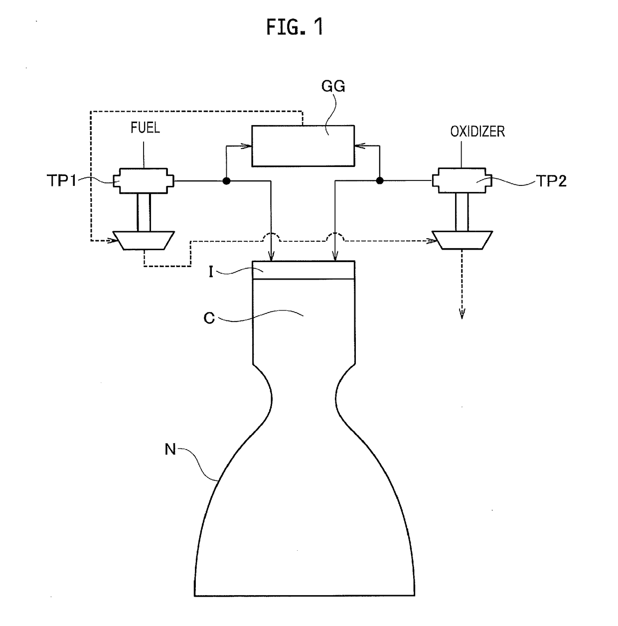
[0023]Hereinafter, an embodiment of the present disclosure will be described with reference to the drawings. FIG. 1 is an explanatory view illustrating a schematic configuration of a liquid rocket engine to which the present disclosure is applied.

[0024]The liquid rocket engine illustrated in FIG. 1 includes a main combustion chamber C having a main injector I and a nozzle N communicating with the main combustion chamber C. Furthermore, the liquid rocket engine includes a turbopump TP1 for supplying fuel to the main injector I in a pressurized manner, and a turbopump TP2 for supplying oxidizer to the main injector I in a pressurized manner. Note that, for example, liquefied natural gas (LNG: liquefied methane) can be used as the fuel. Moreover, for example, liquefied oxygen (LOX) can be used as the oxidizer. There can be used, as the turbopump, single-shaft turbopump in which a turbopump for fuel and a turbopump for oxidizer are integrated.

[0025]Furthermore, the liquid rocket engine ...


PUM


Abstract

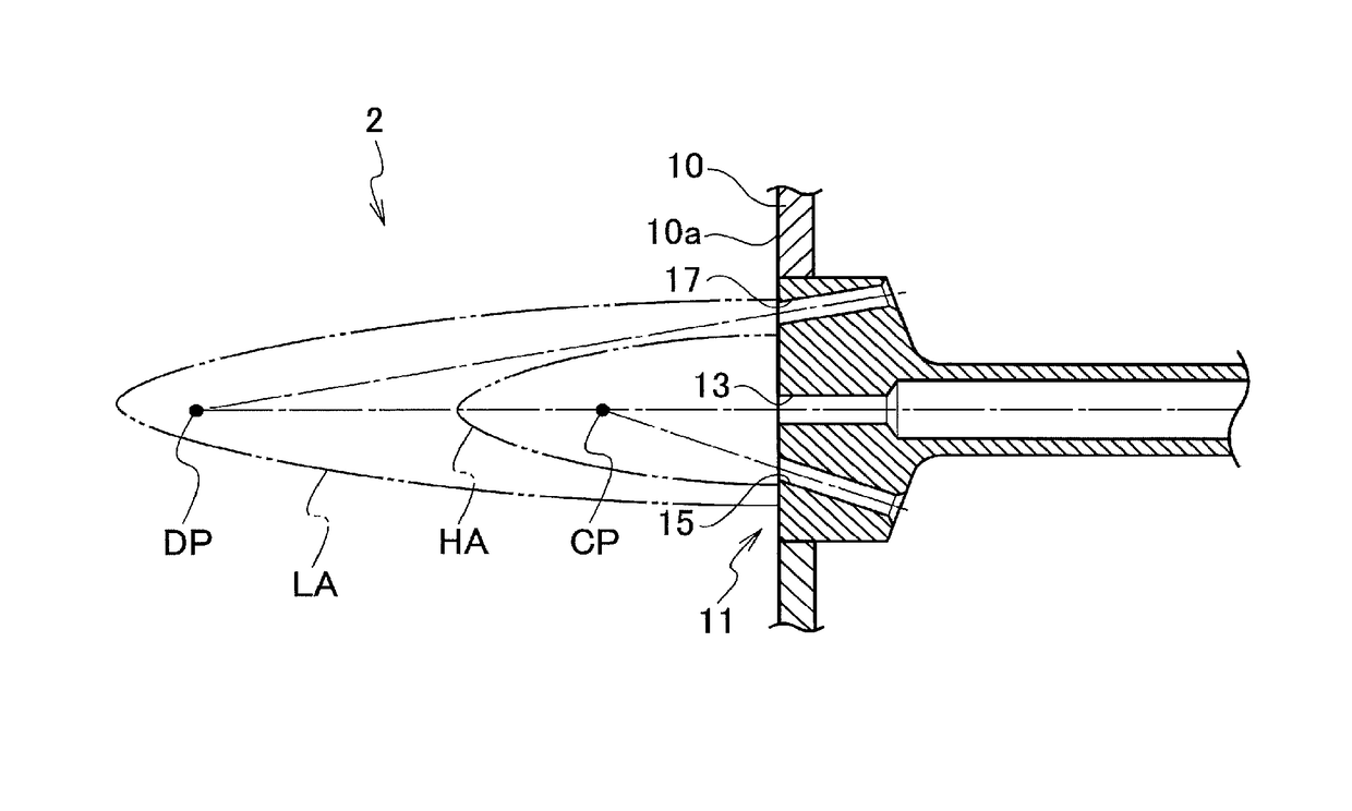
A gas generator includes an injector that injects a fuel and an oxidizer, and a combustor that mixes and burns the fuel and the oxidizer injected from the injector. The injector includes a plurality of injection elements arranged on a face plate. Each of the injection elements includes unlike-impingement type injection nozzles that inject the fuel and the oxidizer toward a combustion point in front of the face plate, and injection nozzles that inject fuel for dilution to a dilution point DP forward further than the combustion point.

Description

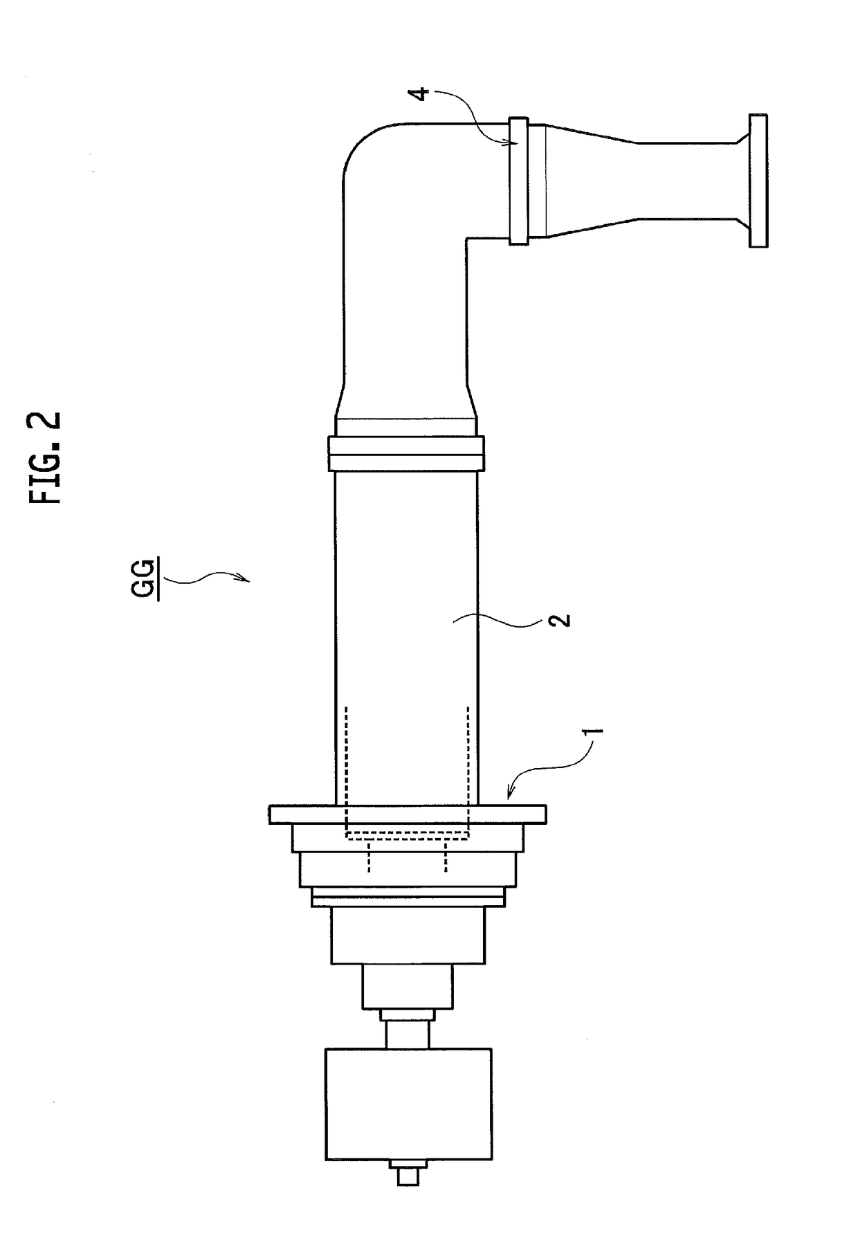
CROSS REFERENCE TO RELATED APPLICATIONS[0001]This application is a continuation application of International Application No. PCT / JP2014 / 071486, filed on Aug. 15, 2014, which claims priority to Japanese Patent Application No. 2013-213725, filed on Oct. 11, 2013, the entire contents of which are incorporated by reference herein.BACKGROUND[0002]1. Technical Field[0003]The present disclosure relates to a gas generator that mixes and burns a fuel and an oxidizer.[0004]2. Description of the Related Art[0005]In a rocket engine, a fuel and an oxidizer are each pressurized by a turbopump, and are supplied to a main combustion chamber. At this time, a part of the fuel and the oxidizer is introduced into a gas generator and is burned, and the resulting combustion gas is supplied as a turbine driving fluid for each of the turbopumps for fuel and oxidizer.[0006]The combustion gas supplied from the gas generator to the turbopumps is required to have low temperatures from the viewpoint of durabili...

Claims


Application Information

Patent Timeline
Patent Type & Authority Patents(United States)
IPC IPC(8): F02K9/52F02K9/62F02C3/20F02C7/22F02K9/44
CPCF02K9/52F02C3/20F02K9/62F02C7/222F02K9/44F02C7/22
Inventor TAYA, KOHEIISHIKAWA, YASUHIRO
Owner IHI CORP
Learn More