Unlock instant, AI-driven research and patent intelligence for your innovation.

Main spindle failure detection device for machine tool and method of detecting main spindle failure

a technology of failure detection and main spindle, which is applied in the direction of testing/monitoring control systems, program control, instruments, etc., can solve the problems of long time for accurate failure diagnosis, inconvenient operation, and high cost, so as to prevent accidental machine stoppage and improve the accuracy of failure determination

Active Publication Date: 2018-09-25
OKUMA CORP
View PDF6 Cites 1 Cited by
  • Summary
  • Abstract
  • Description
  • Claims
  • Application Information

AI Technical Summary

Benefits of technology

The patent text describes a method to improve the accuracy of failure diagnosis in a machine system. By measuring the time it takes to reach a certain speed and comparing it to a preset time, the method can detect and prevent failures even if the diagnosis is not performed perfectly. This prevents accidental machine stoppage and ensures efficient operation.

Problems solved by technology

The main spindle causes a breakdown such as a seizure and a rotation failure due to excessive or insufficient frictional torque with respect to the shaft caused by a poor lubrication, contamination with foreign matter, an excessive load, and an abrasion.
However, with the device as described in Patent document 1, which analyzes the vibration, although time required to detect a failure is short, it is necessary to have a sensor to measure the vibration, resulting in an expensive cost.
However, since the change in rotation speed with respect to elapsed time shows non-linearity as a lubrication state of a bearing changes, the amount of change in rotation speed per unit time is not constant.
It takes a long time for an accurate failure diagnosis including the change in lubrication state, and therefore the diagnosis cannot be executed on a daily basis.

Method used


Image

  • Main spindle failure detection device for machine tool and method of detecting main spindle failure
  • Main spindle failure detection device for machine tool and method of detecting main spindle failure
  • Main spindle failure detection device for machine tool and method of detecting main spindle failure

Examples


Embodiment Construction

[0020]The following describes embodiments of the present disclosure with reference to the drawings.

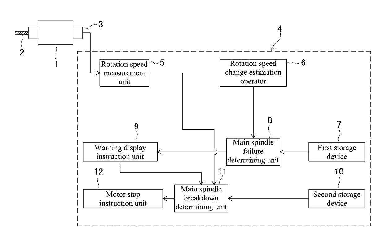
[0021]FIG. 1 is a function block diagram of a main spindle failure detection device. In FIG. 1, a main spindle 1 for a machine tool and a tool 2 are illustrated. A rotation speed detector 3 is disposed at the main spindle 1. A failure detector 4 includes a rotation speed measurement unit 5 that measures a rotation speed of the main spindle 1 during an inertia operation based on a detection signal from the rotation speed detector 3. The rotation speed measurement unit 5 serves as rotation speed detection means of the disclosure together with the rotation speed detector 3.

[0022]The failure detector 4 includes a rotation speed change estimation operator 6 as reach time estimation means, a main spindle failure determining unit 8 as determining means, and a warning display instruction unit 9. The rotation speed change estimation operator 6 estimates time in which a rotation speed reaches a ...


PUM


Abstract

A main spindle failure detection device for a machine tool includes a rotation speed detection unit, a reach time estimation unit, and a determining unit. The reach time estimation unit is configured to estimate a reach time in which the rotation speed of the main spindle reaches a predetermined rotation speed threshold using a non-linear model based on a rotation speed of the main spindle detected at a start of an inertia operation and a rotation speed of the main spindle detected after an elapse of preset measurement time from the start of the inertia operation. The determining unit is configured to compare the reach time estimated by the reach time estimation unit with a preset reach time in which the rotation speed reaches the rotation speed threshold, so as to determine a failure in the main spindle based on a result of the comparison.

Description

BACKGROUND[0001]This application claims the benefit of Japanese Patent Application Number 2015-205780 filed on Oct. 19, 2015 the entirety of which is incorporated by reference.TECHNICAL FIELD[0002]The disclosure relates to a device that detects a failure in a main spindle disposed in a machine tool and a method of the same.RELATED ART[0003]A main spindle for a machine tool is constituted of a shaft, which is a rotator, a bearing that supports the shaft, a seal that prevents contamination of an external foreign object, and a similar member. The main spindle causes a breakdown such as a seizure and a rotation failure due to excessive or insufficient frictional torque with respect to the shaft caused by a poor lubrication, contamination with foreign matter, an excessive load, and an abrasion. In case of the breakdown of the main spindle during processing with the machine tool, it has no choice but to suspend use of the machine tool until the main spindle is exchanged or repaired.[0004]...

Claims


Application Information

Patent Timeline
Patent Type & Authority Patents(United States)
IPC IPC(8): B23Q17/10G05B19/00B23Q17/00
CPCB23Q17/10G05B19/00B23Q17/008B23Q17/00G05B19/0428G05B23/0235G05B19/4065G05B2219/37233G05B2219/37242
Inventor YAMAMOTO, SEIEIKAWADA, NAOKI
Owner OKUMA CORP