

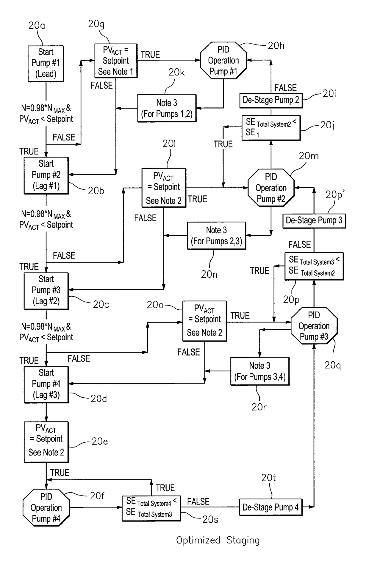
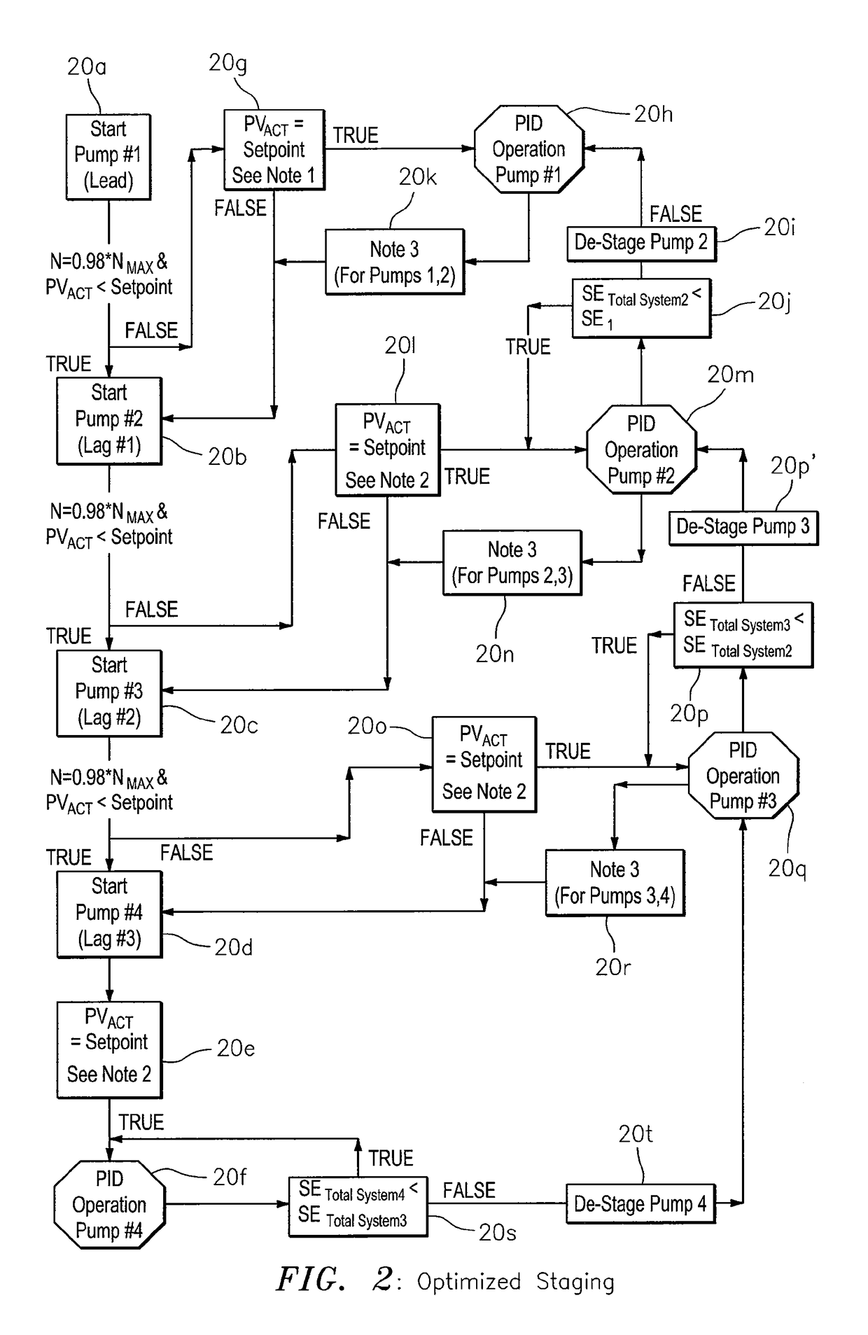
Optimized technique for staging and de-staging pumps in a multiple pump system
a technology of multiple pump system and staging technique, which is applied in the direction of pump control, flow control using electric means, non-positive displacement fluid engine, etc., can solve the problems of multiple pump system setup, cumbersome and time-consuming, and difficult to determine the appropriate de-stage value without trial, so as to improve the overall system reliability, the effect of reducing the cost and being easy to setup
- Summary
- Abstract
- Description
- Claims
- Application Information
AI Technical Summary
Benefits of technology
Problems solved by technology
Method used
Image

Examples
Embodiment Construction
FIG. 1: The Basic Apparatus 10
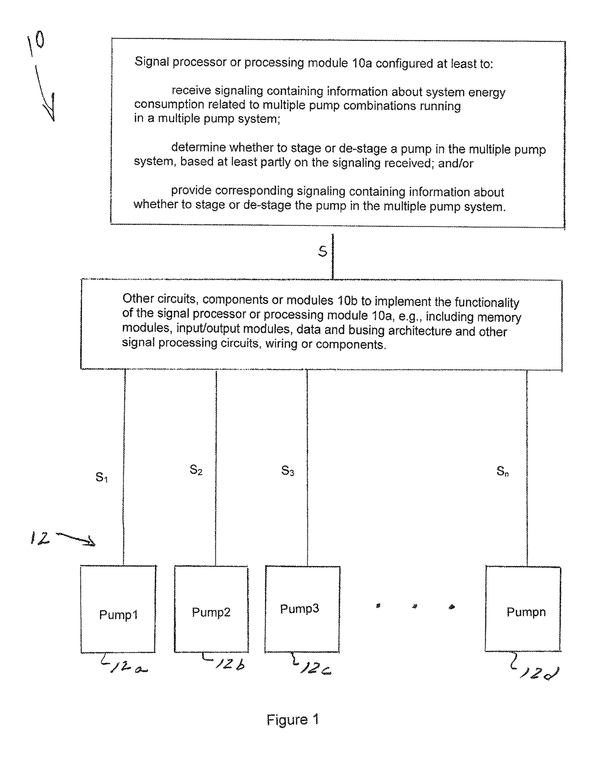
[0079]FIG. 1 shows apparatus generally indicated as 10 for implementing some embodiments of the present invention.
[0080]By way of example, the apparatus 10 may include, or take the form of, a signal processor or processing module 10a for implementing signal processing functionality associated with the present invention. In operation, the signal processor or processing module 10a may be configured at least to:[0081]receive signaling S containing information about system energy consumption related to multiple pump combinations running in a multiple pump system generally indicated as 12; and[0082]determine whether to stage or de-stage a pump in the multiple pump system 12, based at least partly on the signaling S received.
[0083]In FIG. 1, the apparatus 10 may include other circuits, components or modules 10b, e.g., arranged between the multiple pump system 12 and the signal processor or processing module 10a. The other circuits, components or modules 10b m...
PUM
 Abstract
Description
Claims
Application Information