Manipulator and manipulator system

a manipulator and manipulator technology, applied in the field of manipulators and manipulators, can solve problems such as inability to ensure power transmission

Active Publication Date: 2018-10-02
OLYMPUS CORP
View PDF27 Cites 745 Cited by
  • Summary
  • Abstract
  • Description
  • Claims
  • Application Information

AI Technical Summary

Benefits of technology

[0002]The present invention relates to a manipulator and a manipulator system, each having an operating assembly mechanically connected to a moving assembly.

Problems solved by technology

With the manipulator disclosed in JP(A) 2009-201607, however, there is no power transmission ensured when no sufficient tension is applied to the wire routed around and between the driving pulley and the driven pulley.

Method used


Image

  • Manipulator and manipulator system
  • Manipulator and manipulator system
  • Manipulator and manipulator system

Examples


first embodiment

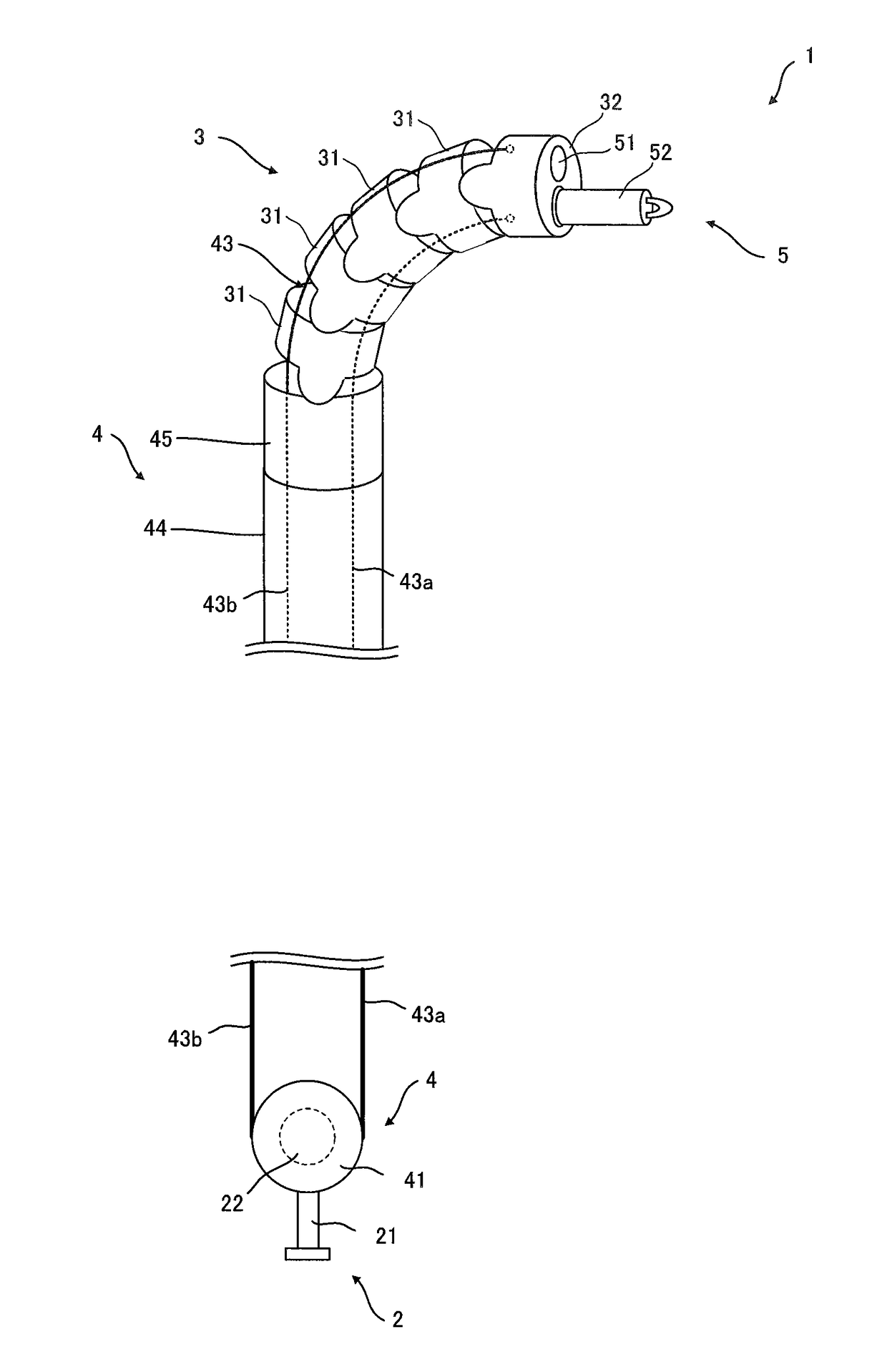
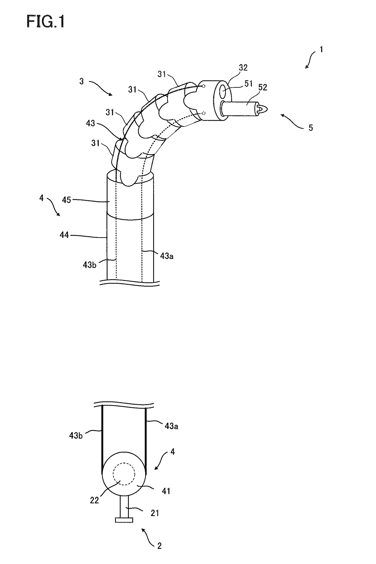
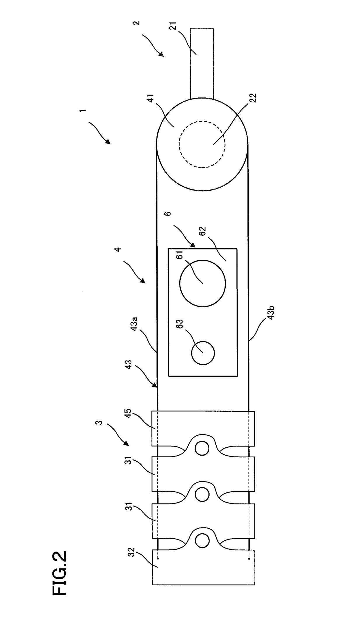
[0044]The first example of the manipulator 1 according to the invention comprises an operating assembly 2, a moving assembly 3, a transmitting assembly 4, and a transmission compensating assembly 6. The operating assembly 2, moving assembly 3, and transmitting assembly 4 may be constructed in the same way as explained with reference to FIG. 1.

[0045]The transmission compensating assembly 6 includes a compensating motor 61, a moving member 62, and an urging member 63. The compensating motor 61 comprises an actuator such as a motor to move the moving member 62 and urging member 63. The urging member 63 is supported on the moving member 62, and rotates together with the moving member 62 to urge the transmitting wire 43 in the transmitting assembly 4.

[0046]The first example of the manipulator 1 according to the first embodiment of the invention is actuated as follow.

[0047]When an operator (not shown) rotates the handle 21 from a neutral state shown in FIG. 2 in a direction indicated by a...

second embodiment

[0107]FIGS. 10A-10B are illustrative in schematic of the first example of the manipulator 1 according to the invention.

[0108]Referring to the first example of the manipulator 1 according to the second embodiment shown in FIGS. 10A-10B, the operating assembly 2 and transmission compensating assembly 6 in the first example of the manipulator 1 according to the first embodiment described here are partly modified in construction. The rest of the manipulate 1 may be the same as explained with reference to FIG. 1; so they will not be explained any more.

[0109]In the manipulator 1 shown in FIGS. 10A-10B, the operating assembly 2 includes a handle 21, a first encoder 22, and a first clutch 65, and the transmission compensating assembly 6 in the manipulator 1 includes a compensating motor 66, and a second encoder 67.

[0110]The handle 21 provides an operating member, the first encoder 22 provides an operating state acquisition member, and the first clutch 65 provides an operating disengagement ...


PUM


Abstract

The invention has for its object to provide a manipulator and manipulator system in which a dynamic surplus is rapidly removed and a moving assembly actuates rapidly in association with the operation of an operating assembly.The manipulator 1 includes an operating assembly 2 operated by an operator, a moving assembly 3 operated by the operating assembly 2, a transmitting assembly 4 for coupling the operating assembly 2 to the moving assembly 3 to transmit driving force of the operating assembly 2 to the moving assembly 3, and a transmission compensating assembly 6 for making up for a dynamic surplus occurring in the transmitting assembly 4 in association with the operation of the operating assembly 2.

Description

CROSS-REFERENCE TO RELATED APPLICATIONS[0001]This application is a continuation claiming priority on the basis of Japan Patent Application No. 2013-155480 applied in Japan on Jul. 26, 2013 and based on PCT / JP2014 / 067792 filed on Jul. 3, 2014. The contents of both the PCT application and the Japan Application are incorporated herein by reference.BACKGROUND OF THE INVENTION AND RELATED ART STATEMENT[0002]The present invention relates to a manipulator and a manipulator system, each having an operating assembly mechanically connected to a moving assembly.[0003]So far there has been a manipulator disclosed in Patent Publication 1, wherein one end of a wire inserted through a hollow shaft is routed around a driving pulley and the other end is done around a driven pulley for power transmission.[0004]With the manipulator disclosed in JP(A) 2009-201607, however, there is no power transmission ensured when no sufficient tension is applied to the wire routed around and between the driving pull...

Claims


Application Information

Patent Timeline
Patent Type & Authority Patents(United States)
IPC IPC(8): A61B1/005A61B1/04A61B1/00B25J3/04B25J9/16A61B1/06A61B1/018A61B34/00
CPCA61B1/0057A61B1/0052A61B1/04A61B1/06A61B34/70A61B34/71B25J3/04B25J9/1689A61B1/00045G05B2219/49253A61B1/00006A61B1/018A61B2034/715G05B2219/35417G05B2219/39439G05B2219/45118
Inventor ISODA, TAKUMIHATAKEYAMA, NAOYAIIDA, MASATOSHIWATANABE, SADAHIRO
Owner OLYMPUS CORP
Why Eureka
Try Eureka