
Remote operation device

a remote operation and control device technology, applied in the field of remote operation devices, can solve the problems of user's inability to select the controlled item, user's tilting the rotary disc (support shaft) of the operation acceptance portion too much or too, and the inability to operate the in-vehicle device using the remote operation device in the related ar

Inactive Publication Date: 2018-10-09
DENSO CORP
View PDF13 Cites 0 Cited by
  • Summary
  • Abstract
  • Description
  • Claims
  • Application Information

AI Technical Summary

Benefits of technology

The remote operation device described in this patent aims to reduce the likelihood of users accidentally hitting the wrong button and triggering an unwanted operation. This results in a more efficient and streamlined user experience.

Problems solved by technology

It is, however, difficult to operate the in-vehicle device using the remote operation device in the related art because the user operates the operation acceptance portion against a force generated in the reactive force generation portion.
The user may tilt the rotary disc (support shaft) of the operation acceptance portion too much or too little.
In such a case, the user may possibly fail to select the controlled item the user originally intended to select.
Hence, the remote operation device in the related art has a problem that the user rotates the rotary disc even when a different controlled item is selected contrary to the user's intention, and an input of a control amount of a different content is accepted instead of a control amount of the content that should have been inputted.
In other words, the remote operation device in the related art has a drawback that an input of a content different from a content of an operation the user originally intended to make is accepted by an erroneous operation.

Method used


Image

  • Remote operation device
  • Remote operation device
  • Remote operation device

Examples


Embodiment Construction

[0029]Hereinafter, embodiments of the present disclosure will be described with reference to the drawings.

Remote Operation Device

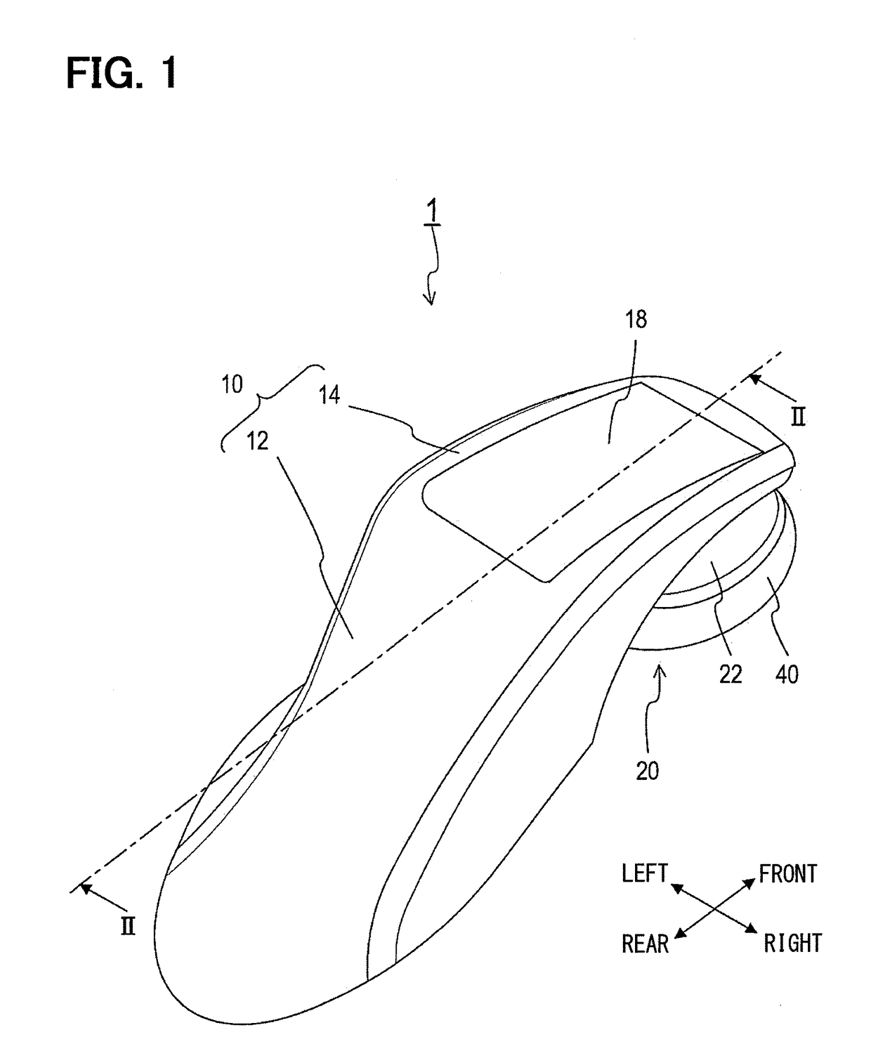
[0030]A remote operation device 1 shown in FIG. 1 is a device to enable a user to operate an in-vehicle device 90 (see FIG. 4) installed to an automobile by remote control without directly touching the in-vehicle device 90. The in-vehicle device 90 referred to herein is an example and includes various types of devices installed to an automobile. The in-vehicle device 90 can be, for example, an in-vehicle navigation system (so-called car navigation system) that guides the user along a route to a destination, an air conditioner (in-vehicle air conditioner) that adjusts a temperature in a vehicle interior, and an audio instrument.

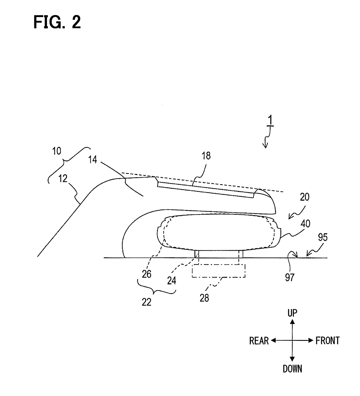
[0031]The remote operation device 1 is attached to a predetermined portion (hereinafter, referred to as an attached portion) 95 (see FIG. 2) of the automobile. For example, the attached portion 95 of the present embodiment is on top ...


PUM


Abstract

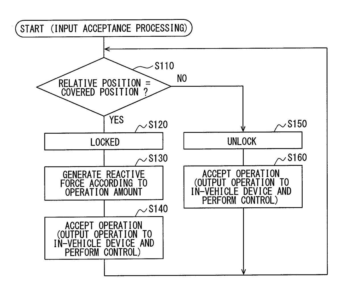
A remote operation device includes a first operation acceptance portion having a rotary dial, a second operation acceptance portion provided along an outer periphery of the rotary dial and allowed to rotate separately from the rotary dial, and a control portion. When a relative position of a user's hand with respect to the first operation acceptance portion is at a covered position, the control portion switches the first operation acceptance portion and the second operation acceptance portion to a locked state and accepts an operation on the first operation acceptance portion. When the relative position of the user's hand with respect to the first operation acceptance portion is at an uncovered position, the control portion switches the first operation acceptance portion and the second operation acceptance portion to an unlocked state and accepts an operation on the second acceptance portion.

Description

CROSS REFERENCE TO RELATED APPLICATIONS[0001]This application is a U.S. National Phase Application under 35 U.S.C. 371 of International Application No. PCT / JP2015 / 000661 filed on Feb. 13, 2015 and published in Japanese as WO 2015 / 125445 A1 on Aug. 27, 2015. This application is based on and claims the benefit of priority from Japanese Patent Application No. 2014-031711 filed on Feb. 21, 2014. The entire disclosures of all of the above applications are incorporated herein by reference.TECHNICAL FIELD[0002]The present disclosure relates to a remote operation device to operate a device installed to a mobile body by remote control.BACKGROUND ART[0003]A remote operation device in the related art enables a user to operate an in-vehicle device installed to an automobile by remote control without directly touching the in-vehicle device (see Patent Literature 1).[0004]The remote operation device as above is attached to an attached portion, which is a predetermined portion of the automobile. T...

Claims


Application Information

Patent Timeline
Patent Type & Authority Patents(United States)
IPC IPC(8): G05G9/047H01H25/06H03K17/96B60K37/06H01H9/20H01H25/04H01H3/00B60K35/10
CPCG05G9/047B60K37/06H01H25/065H03K17/962H01H2221/052H01H9/20H01H25/04H01H2003/008H01H2217/034G05G2009/04766G06F3/0338H01H25/06G06F2203/0332G06F3/0362G06F3/03547G05G1/08G06F3/016B60K35/10B60K2360/137B60K2360/126B60K2360/143B60K35/00
Inventor HAYASHI, KAZUMI
Owner DENSO CORP
Learn More