
Reduction of cross-talk between RF components in a mass spectrometer

a mass spectrometer and cross-talk technology, applied in the field of mass spectrometry, can solve the problems of system performance degradation of the mass spectrometer, unwanted perturbations, and change in mass resolution of the mass analyzer

Active Publication Date: 2015-01-08
BRUKER DALTONIK GMBH & CO KG
View PDF2 Cites 0 Cited by
  • Summary
  • Abstract
  • Description
  • Claims
  • Application Information

AI Technical Summary

Benefits of technology

Effectively eliminates cross-talk between RF components, maintaining high ion transmission and stable mass analysis properties without geometrical acceptance degradation or electric field distortions, thus enhancing system performance and simplifying tuning.

Problems solved by technology

The close proximity of the RF components results in RF coupling or cross-talk therebetween, which causes unwanted perturbations from one RF component on the other adjacent RF component.
As a result of these external perturbations, the system performance of the mass spectrometer is degraded.
For example, external perturbations on a mass analyzer as a consequence of RF coupling with an adjacent RF component can cause the mass resolution of the mass analyzer to change.
Because resolution is related to the ion transmission of the mass analyzer, the overall sensitivity of the measurement will also be affected, which is undesirable.
However, due to the lenses being arranged in between the end-faces of the adjacent RF components they also influence the ion transmission characteristics by, for instance, reducing the geometrical acceptance of the respective downstream RF component and also by creating an additional surface where stray ions can hit, charge-up and create an electric field distortion.
The latter, in particular, increases the optimization complexity of the instrument.
This design generally works well, but requires additional effort and expense when fabricating the multipole electrodes to also include the extensions, and properly align them with those of another multipole RF component.

Method used


Image

  • Reduction of cross-talk between RF components in a mass spectrometer
  • Reduction of cross-talk between RF components in a mass spectrometer
  • Reduction of cross-talk between RF components in a mass spectrometer

Examples


Embodiment Construction

[0031]While the invention has been shown and described with reference to a number of embodiments thereof, it will be recognized by those skilled in the art that various changes in form and detail may be made herein without departing from the spirit and scope of the invention as defined by the appended claims.

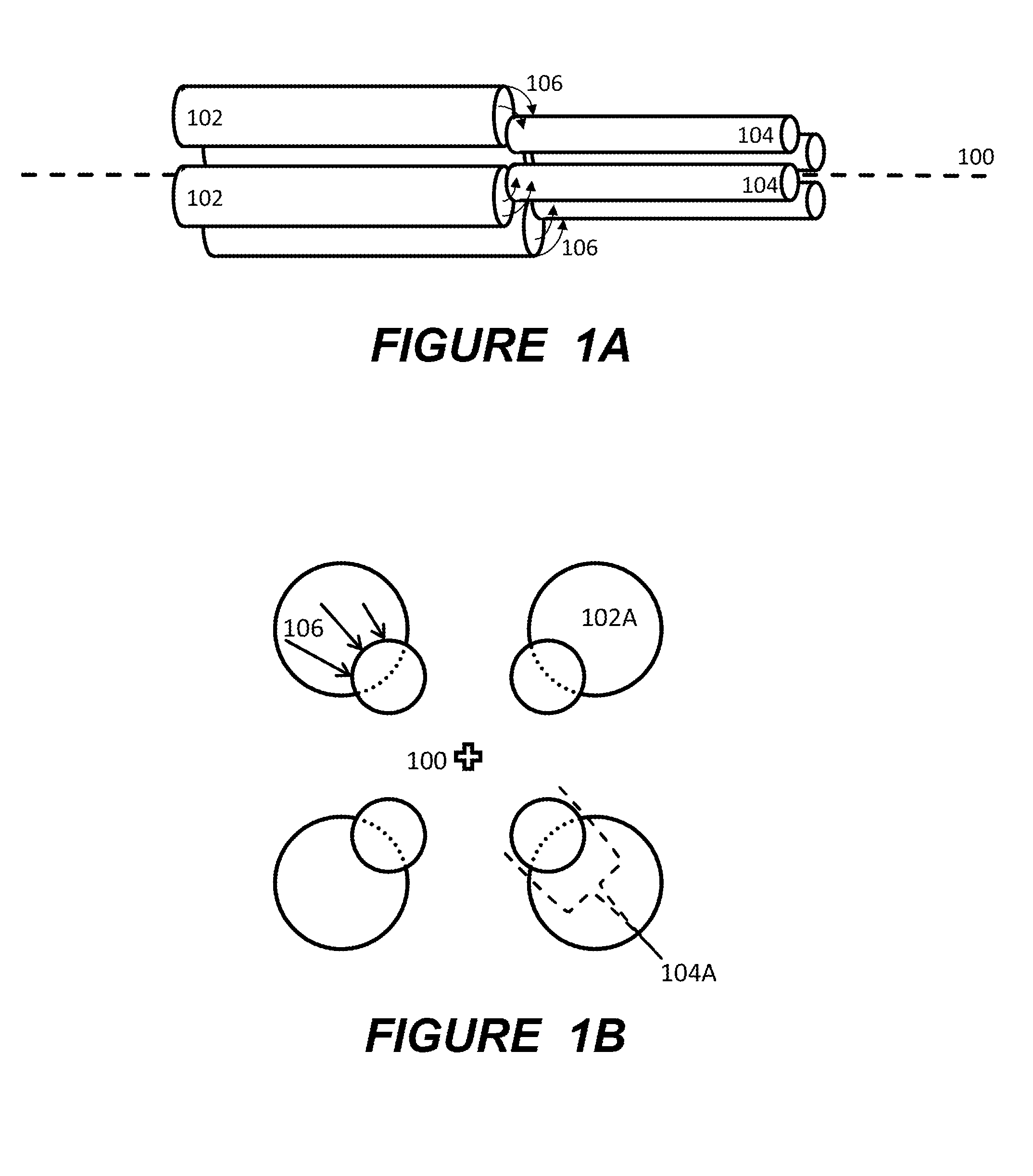
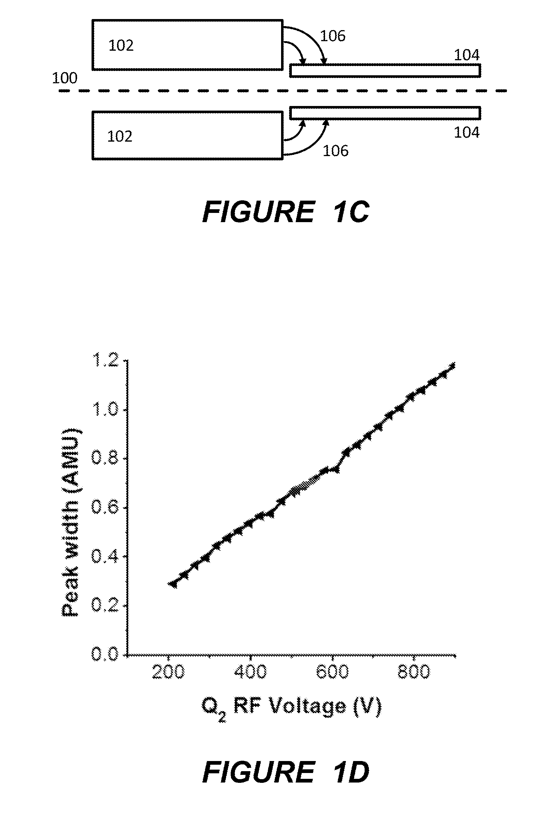
[0032]FIGS. 1A to 1C schematically show a lens-free and screen-free tandem quadrupole assembly in different views. FIG. 1A depicts a pseudo-isometric view; FIG. 1B a front-end view from right to left as seen in FIG. 1A; and FIG. 1C a plain lateral view.

[0033]In this example, the transverse dimension of the pole electrodes in relation to the longitudinal axis 100 differs between the two quadrupoles so that there is one quadrupole with thick electrodes 102 (FIGS. 1A and 1C: on the left) and another quadrupole with thin electrodes 104 (FIGS. 1A and 1C: on the right). The pole electrodes 102, 104 displayed uniformly have the shape of rods and as such a circular cross section which, ...


PUM


Abstract

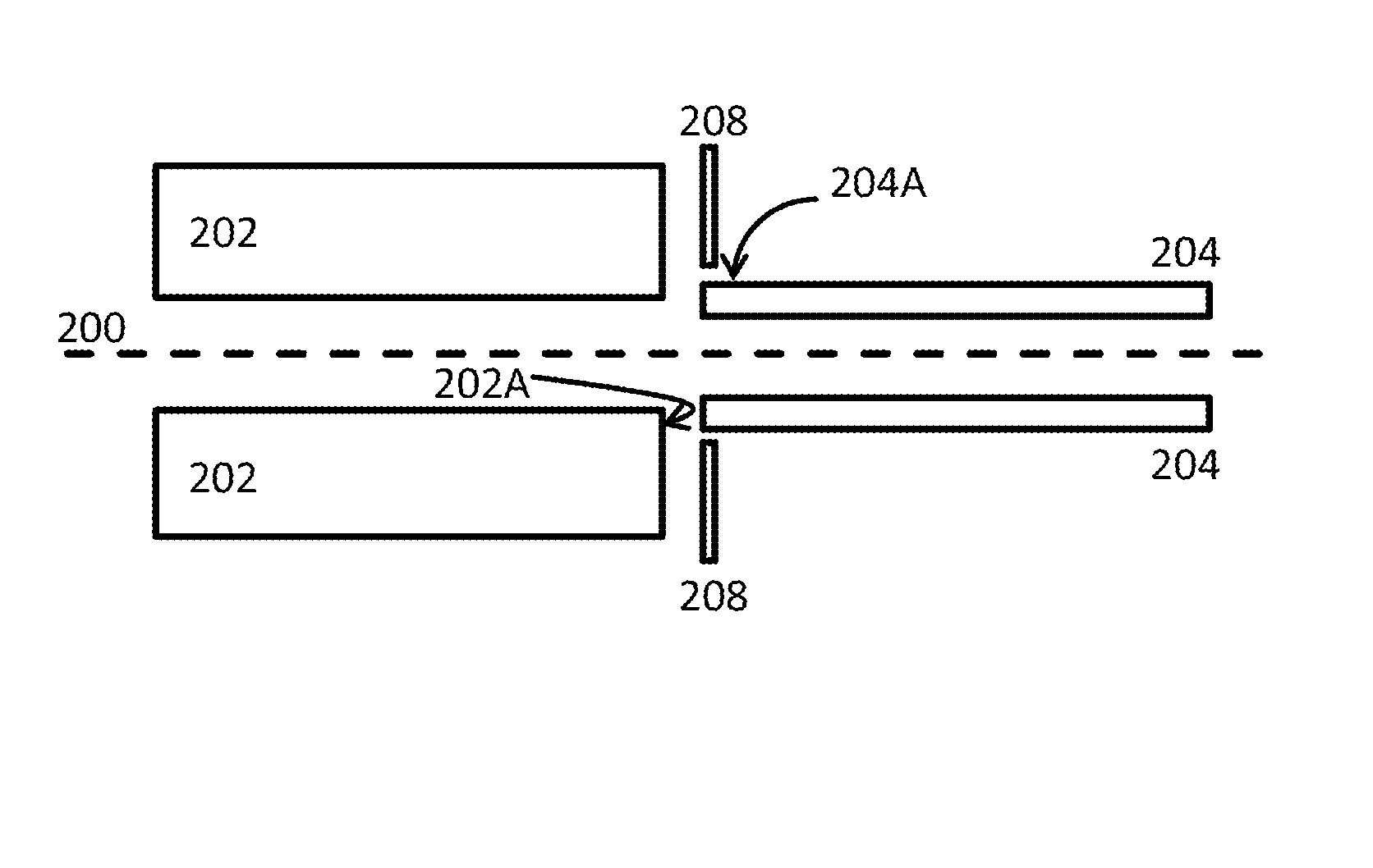
The invention generally relates to an assembly of a first RF component and a second RF component in a mass spectrometer, the first RF component comprising a first set of electrodes and the second RF component comprising a second set of electrodes, wherein the RF components are located and aligned end-to-end to one another, and wherein a transverse dimension of the electrodes of the first set is smaller than that of the electrodes of the second set. The assembly further comprises a conductive electric field screen located at an outer periphery of the first set of electrodes and facing the electrodes of the second set as to reduce RF electric field cross-talk between the electrodes of the first set and those of the second set. The invention affords for technically simple and economic means to reduce cross-talk or capacitive coupling between adjacent RF components in a mass spectrometer.

Description

BACKGROUND OF THE INVENTION[0001]1. Field of the Invention[0002]This invention relates generally to the field of mass spectrometry and, more specifically, to the reduction of cross-talk between RF components of a mass spectrometer.[0003]2. Description of the Related Art[0004]Nowadays, RF components are standard devices for use in mass spectrometry. Examples of RF components used in a mass spectrometer include multipole ion guides, multipole mass analyzers (sometimes also called mass filters), pre / post filters, multipole collision cells, and multipole ion traps. Such RF components may be implemented using a configuration having an even number of elongate pole electrodes arranged equi-angularly on a circular perimeter about a common axis. This axis may be linear or non-linear, such as curved. Some mass spectrometers use RF components in tandem or adjacent to one another. Examples of such tandem devices can be found in U.S. Pat. No. 6,191,417 B1 (Douglas et al.) and U.S. Pat. No. 6,340...

Claims


Application Information

Patent Timeline
Patent Type & Authority Applications(United States)
IPC IPC(8): H01J49/06
CPCH01J49/06H01J49/063H01J49/4215
Inventor MUNTEAN, FELICIANMOELLER, ROYZANON, STEPHEN
Owner BRUKER DALTONIK GMBH & CO KG
Learn More