
Multilayer ceramic capacitor having dielectric layers containing ceramic grains constituted by primarily BaTiO3 and additionally Mo, Mn, R, and V/W

a multi-layer ceramic and ceramic capacitor technology, applied in the field of multi-layer ceramic capacitors, can solve problems such as magnification of leak current problems, and achieve the effect of improving service life characteristics

Active Publication Date: 2018-10-09
TAIYO YUDEN KK
View PDF18 Cites 1 Cited by
  • Summary
  • Abstract
  • Description
  • Claims
  • Application Information

AI Technical Summary

Benefits of technology

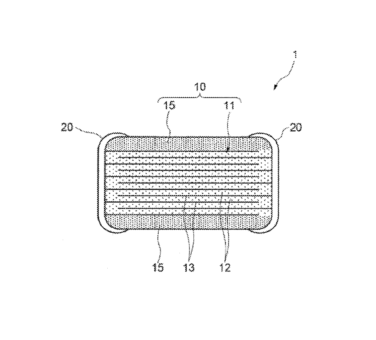
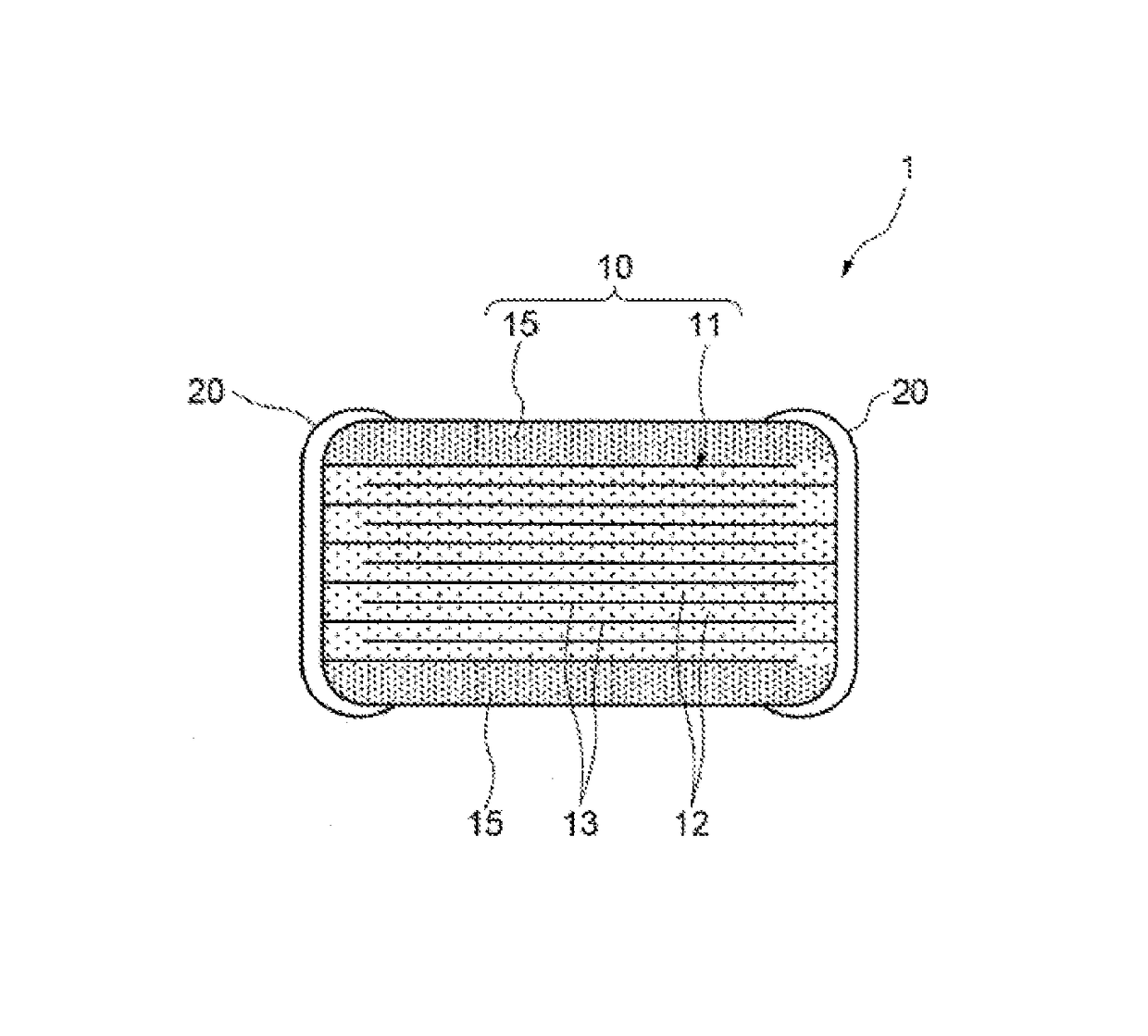
[0011]Also, when dielectric layers become thinner, shorting occurs between the internal electrodes that are stacked in a manner alternately led out to the external electrodes on the opposite sides, which magnifies the problem of leak current.
[0023]According to the present invention, a multilayer ceramic capacitor offering excellent service life characteristics and sufficiently suppressing leak current even when the thickness of the dielectric layer is 0.8 μm or less, is provided.

Problems solved by technology

Also, when dielectric layers become thinner, shorting occurs between the internal electrodes that are stacked in a manner alternately led out to the external electrodes on the opposite sides, which magnifies the problem of leak current.

Method used


Image

  • Multilayer ceramic capacitor having dielectric layers containing ceramic grains constituted by primarily BaTiO<sub>3 </sub>and additionally Mo, Mn, R, and V/W
  • Multilayer ceramic capacitor having dielectric layers containing ceramic grains constituted by primarily BaTiO<sub>3 </sub>and additionally Mo, Mn, R, and V/W

Examples


example 1

[0071]BaCO3 (specific surface area 30 m2 / g) and TiO2 (specific surface area 50 m2 / g) were added to an aqueous solution of ion-exchanged water to which dispersant was added, in such a way that the Ba / Ti mol ratio became 1, and the obtained slurry was mixed / dispersed using a bead mill. The slurry was dried to remove water, and then tentatively sintered at 935° C. to synthesize BaTiO3 of 100 nm in average grain size based on a SEM photograph.

[0072]Next, the various additive materials were added at the ratios of MoO3=0.2 mol, (Ho2O3) / 2=0.75 mol, MnCO3=0.03 mol, WO3=0.184 mol, and SiO2=1.0 mol per 100 mol of BaTiO3 (all equivalent values as each chemical compound), after which solvent was added to obtain a slurry. PVB binder was added to the slurry and the slurry was applied on a PET film to a thickness of 1.0 μm to obtain a green sheet.

[0073]Next, a Ni conductive paste was printed on the green sheet as internal electrodes and this was used to produce a 400-layer multilayer ceramic capac...

example 2

[0080]A multilayer ceramic capacitor was produced in the same manner as in Example 1, except that MnCO3 was added by 0.02 mol (equivalent value) and (Ho2O3) / 2 was added by 0.50 mol (equivalent value). As a result, the average valence number of Mo became 4.52. The result of the high-temperature accelerated service life test of the multilayer ceramic capacitor was 470 minutes, and the current value after 30 seconds was 95 μA.

example 3

[0081]A multilayer ceramic capacitor was produced in the same manner as in Example 1, except that MnCO3 was added by 0.15 mol (equivalent value) and (Ho2O3) / 2 was added by 1.80 mol (equivalent value). As a result, the average valence number of Mo became 4.90. The result of the high-temperature accelerated service life test of the multilayer ceramic capacitor was 950 minutes, and the current value after 30 seconds was 85 μA.


PUM

PropertyMeasurementUnit
thicknessaaaaaaaaaa
thickaaaaaaaaaa
thicknessaaaaaaaaaa

Abstract

A multilayer ceramic capacitor includes a laminate constituted by internal electrode layers of different polarities alternately layered via dielectric layers, wherein the multilayer ceramic capacitor is such that the dielectric layers contain ceramic grains whose primary component is BaTiO3, the ceramic grains contain Mo, Mn, rare earth R, and at least one of V and W, and the average valence number of Mo in the ceramic grains is 4.50 to 5.50. The multilayer ceramic capacitor can offer excellent service life characteristics and sufficiently suppress leak current even when the thickness of the dielectric layer is 0.8 μm or less.

Description

BACKGROUND[0001]Field of the Invention[0002]The present invention relates to a multilayer ceramic capacitor whose dielectric layers are constituted by ceramic grains of a specific composition.[0003]Description of the Related Art[0004]In recent years, there is a high demand for smaller electronic components to support increasingly dense electronic circuits used in mobile phones, tablet terminals, and other digital electronic devices, and multilayer ceramic capacitors (MLCC) that constitute these circuits are rapidly becoming smaller in size and larger in capacitance.[0005]The capacitance of a multilayer ceramic capacitor is directly proportional to the dielectric constant of the constitutional material of the dielectric layers constituting the capacitor and also to the number of dielectric layers, and inversely proportional to the thickness of one dielectric layer. Accordingly, meeting the demand for size reduction requires increasing the dielectric constant of the material, while al...

Claims


Application Information

Patent Timeline
Patent Type & Authority Patents(United States)
IPC IPC(8): H01G4/12H01G4/30
CPCH01G4/1227H01G4/30
Inventor KAWAMURA, CHIEOGATA, YOICHIROSHIMURA, TETSUORYU, MINORUIWAZAKI, YOSHIKI
Owner TAIYO YUDEN KK
Learn More