
Method of production of back-contact back-sheet for photovoltaic modules

a photovoltaic module and back-contact technology, applied in photovoltaic energy generation, electrical equipment, sustainable buildings, etc., can solve the problems of reducing affecting the efficiency of the solar module's cells, so as to achieve the effect of simple opening process

Active Publication Date: 2018-10-16
EBFOIL
View PDF10 Cites 0 Cited by
  • Summary
  • Abstract
  • Description
  • Claims
  • Application Information

AI Technical Summary

Benefits of technology

This approach enables the formation of a precise and efficient connecting circuit without causing substrate deformation, ensuring a stable and reliable assembly of photovoltaic modules by maintaining the flatness and quality of the back-contact back-sheet.

Problems solved by technology

The electrical connection in the photovoltaic modules comprising traditional solar cells takes place on both the front and back sides of the cell, causing shading problems.
In particular, the front electrode, namely the electrode exposed to light radiation, is electrically contacted using a technique called “H-patterning”, which generates shading problems on the surface facing the light radiation because of the presence of metallic traces that screen the incident light on the front surface of the cell.
Therefore, traditional electrical contacts lead to a decreased efficiency of the cells of the solar modules.
The back-contact cells pose new technological problems relating to the design and structures of the modules intended to house them.
However, due to thermal expansion, and in particular due to the different expansion coefficients of the different layers, the high temperatures used during the chemical etching normally produce deformations of the back-contact back-sheet.
Consequently, the quality and the reliability of the back-contact back-sheet produced according to the traditional method are compromised.

Method used


Image

  • Method of production of back-contact back-sheet for photovoltaic modules
  • Method of production of back-contact back-sheet for photovoltaic modules
  • Method of production of back-contact back-sheet for photovoltaic modules

Examples


Embodiment Construction

[0039]In the following, the present invention will be described with reference to particular embodiments as shown in the attached figures. However, the present invention is not restricted to the particular embodiments described in the following detailed description and shown in the figures. Rather, the described embodiments simply show several aspects of the present invention whose scope is defined by the claims.

[0040]Further modifications and variations of the present invention will be clear for the person skilled in the art. As a consequence, the present description is to be considered as comprising all modifications and / or variations of the present invention, whose scope is defined by the claims.

[0041]In the following, the expressions “above” or “below” always refer to an imaginary ground plane. The expression “point A above (below) point B” indicates that the distance of point A to the ground plane is longer (shorter) than the distance of point B from the ground plane. Similarly...


PUM


Abstract

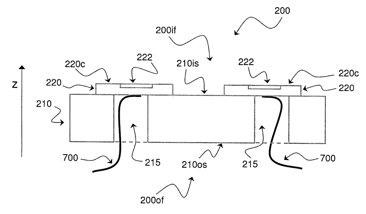
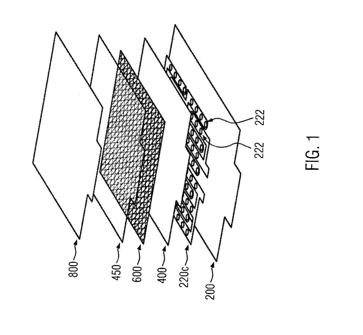
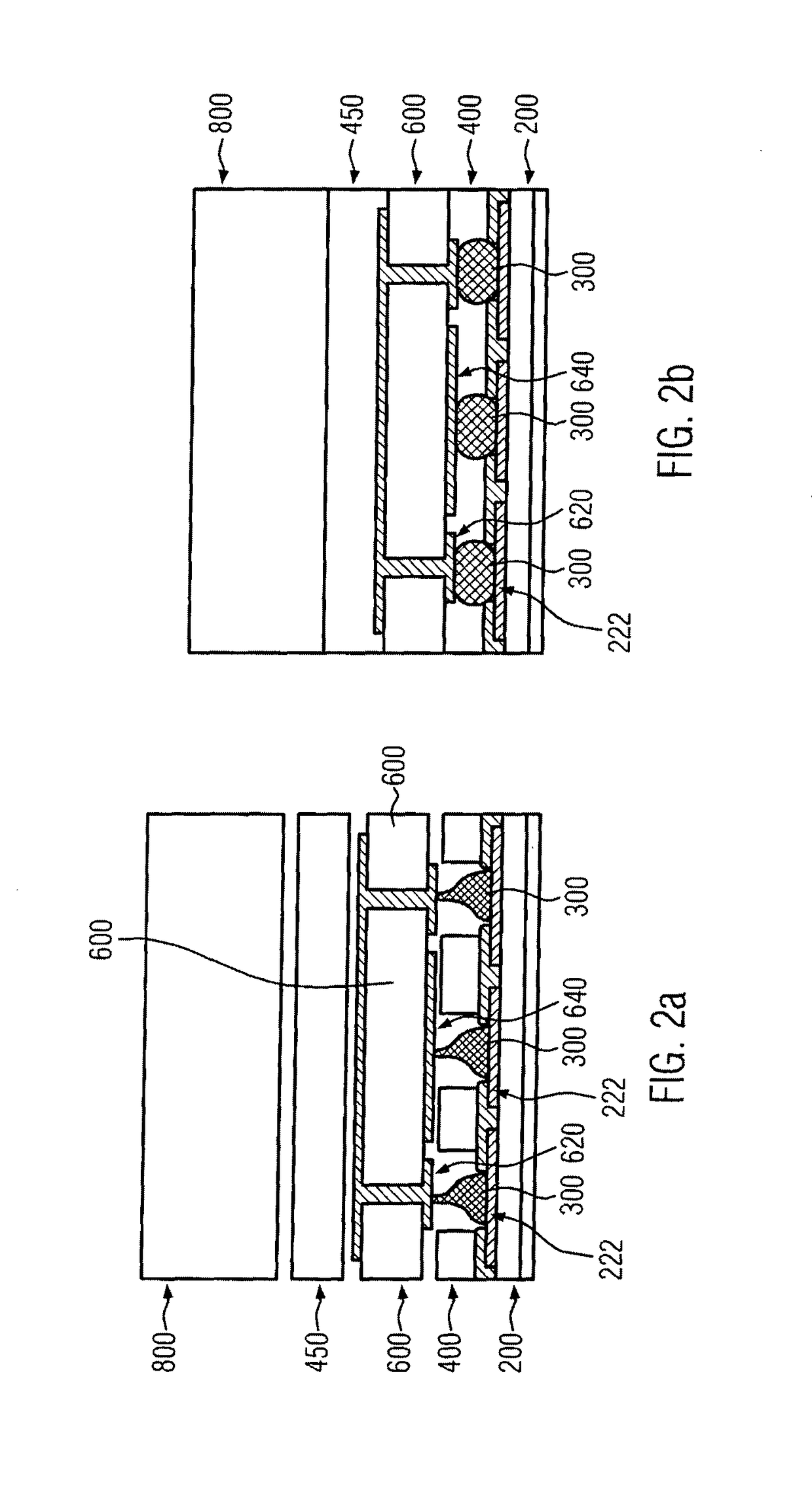
The present invention provides a method for producing a back-contact back-sheet for a photovoltaic module comprising back-contact cells. The method comprising providing a substrate (210) having an outer surface (210os) facing the air-side of the photovoltaic module and an inner surface (210is) opposite the outer surface (210os) and facing the inside of the photovoltaic module. A layer of electrically conductive material (220) adapted to be formed as a connecting circuit (220c) to the electrodes of the solar cells is then applied to the substrate (210). The application of the layer of electrically conductive material (220) to the substrate (210) is performed in such a way that the layer of electrically conductive material (220) fixedly adheres to the inner surface (210is) of the substrate (210). The layer of electrically conductive material (220) is then processed so as to form the connecting circuit (220c). The step of processing the layer of electrically conductive material (220) comprises mechanically milling the layer of electrically conductive material (220), the processing being performed after the application of the layer of electrically conductive material (220) to the substrate (210).

Description

TECHNICAL FIELD OF THE INVENTION[0001]The present invention concerns the field of photovoltaic modules. In particular, the present invention is related to new generation back-contact back-sheets for a photovoltaic module and methods for producing same. More in particular, the present invention is related to a method for producing a back-contact back-sheet in which a mechanical ablation is performed, for example by milling, with the aim of forming the connecting circuit on the inner surface of the back-contact back-sheet. Moreover, the present invention relates to a method of production of a back-contact back-sheet in which the ablation technique has the aim of opening a plurality of windows through the insulating substrate of the back-contact back-sheet so as to connect the connecting circuit to the outer surface of the photovoltaic module. This ablation technique, employed for opening the windows in the insulating substrate of the back-contact back-sheet, may advantageously compris...

Claims


Application Information

Patent Timeline
Patent Type & Authority Patents(United States)
IPC IPC(8): H01L31/05H01L31/0203H01L31/02
CPCH01L31/0516H01L31/0201H01L31/0203Y02E10/50Y02B10/12Y02B10/10
Inventor BACCINI, ELISAMARRAS, LUIGIBUCCI, BRUNO
Owner EBFOIL
Learn More