Flyback power converter circuit with active clamping and zero voltage switching and conversion control circuit thereof

Active Publication Date: 2018-10-16
RICHTEK TECH
View PDF4 Cites 6 Cited by
  • Summary
  • Abstract
  • Description
  • Claims
  • Application Information

AI Technical Summary

Benefits of technology

The patent text describes a method to adjust the timing of signals in a system. When the phase difference between two signals indicates that the zero crossing time point is later than the primary side turning ON time point, the auxiliary dead time (which is the time after the primary side has turned on and before the second signal can start) is lengthened. On the other hand, when the phase difference indicates that the zero crossing time point is earlier than the primary side turning ON time point, the auxiliary dead time is shortened. This allows for better synchronization and timing in the system.

Problems solved by technology

The prior art circuits in FIGS. 1 and 2A-2B have a drawback that the dead time Td between the ON time periods of the auxiliary switch S2 and the primary side switch S1 is fixed length, and therefore the time point when the primary side switch S1 is turned ON may not be a right timing for zero voltage switching (i.e. the time point when the parasitic capacitor Coss is just fully discharged).
The power loss may increase due to missing the right timing.

Method used


Image

  • Flyback power converter circuit with active clamping and zero voltage switching and conversion control circuit thereof
  • Flyback power converter circuit with active clamping and zero voltage switching and conversion control circuit thereof
  • Flyback power converter circuit with active clamping and zero voltage switching and conversion control circuit thereof

Examples


Embodiment Construction

[0034]The drawings as referred to throughout the description of the present invention are for illustration only, to show the interrelations between the circuits and the signal waveforms, but not drawn according to actual scale.

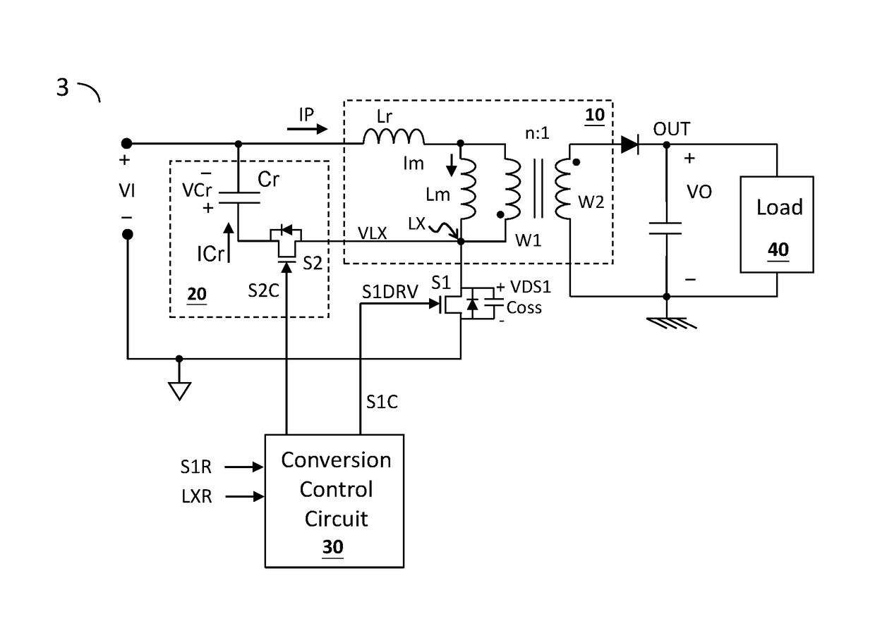
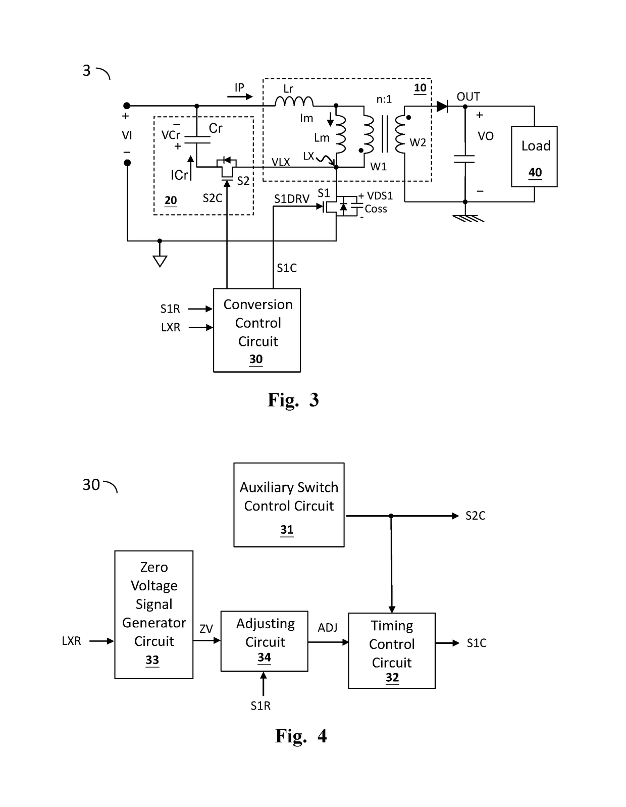
[0035]FIG. 3 shows one embodiment of the flyback power converter circuit with active clamping and zero voltage switching according to the present invention (flyback power converter circuit 3). The flyback power converter circuit 3 comprises a transformer 10, a primary side switch S1, and a conversion control circuit 30. The transformer 10 includes a primary side winding W1 which is electrically coupled to an input power and a secondary side winding W2 which is coupled to an output node OUT, wherein the input power includes an input voltage VI. The primary side switch S1 is coupled to the primary side winding W1, and is configured to operably switch the primary side winding W1 to convert the input power such that the secondary side winding W2 generates an outpu...


PUM


Abstract

A flyback power converter circuit includes: a transformer, including a primary winding coupled to an input power and a secondary winding coupled to an output node; a primary side switch coupled to the primary winding for switching the input power to generate an output power on the output node through the secondary winding; a clamping circuit including an auxiliary switch and an auxiliary capacitor which are connected in series to form an auxiliary branch which is connected with the primary winding in parallel; and a conversion control circuit adjusting an auxiliary dead time according to a primary side switch related signal and a switching voltage related signal such that the primary side switch is zero voltage switching at a time point when the primary side switch is turned ON.

Description

CROSS REFERENCE[0001]The present invention claims priority to U.S. 62 / 486,764, filed on Apr. 18, 2017 and TW 106124274, filed on Jul. 20, 2017.BACKGROUND OF THE INVENTIONField of Invention[0002]The present invention relates to a flyback power converter circuit; particularly, it relates to a flyback power converter circuit with active clamping and zero voltage switching. The present invention also relates to a conversion control circuit for use in the flyback power converter circuit.Description of Related Art[0003]FIG. 1 shows a prior art flyback power converter circuit with active clamping (flyback power converter circuit 1). The flyback power converter circuit 1 converts an input voltage to an output voltage. The flyback power converter circuit 1 includes an auxiliary switch S2 and an auxiliary capacitor Cr which form an active clamping branch. The active clamping branch is ON when the primary side switch S1 is OFF, such that the energy stored in the parasitic leakage inductance Lr...

Claims


Application Information

Patent Timeline
IPC IPC(8): H02M1/08H02M3/335
CPCH02M3/33569H02M1/083H02M3/335H02M1/0058H02M3/01H02M1/38Y02B70/10
Inventor LIN, KUN-YULIN, TZU-CHENCHANG, WEI-HSUYANG, TA-YUNG
Owner RICHTEK TECH
Why Eureka
Try Eureka