Tilting disc check valve

a check valve and tilting disc technology, applied in the direction of machines/engines, pressure relieving devices on sealing faces, liquid fuel engines, etc., can solve the problems of valve rods subjected to radial bending moments, metal hard sealing forms of sealing pairs are not allowed, valve closing impact is eliminated, and the effect of reducing flow resistance and water head loss

Active Publication Date: 2018-10-23
ZHUZHOU SOUTHERN VALVE
View PDF32 Cites 1 Cited by
  • Summary
  • Abstract
  • Description
  • Claims
  • Application Information

AI Technical Summary

Benefits of technology

[0010]A purpose of the invention is to provide a diaphragm control slider type tilting disc check valve, so as to solve the technical problem of slow closing failure of two-stage closing, correct an unreasonable eccentric design, completely eradicate the loosening and disconnection of a slow closing part, eliminate valve closing impact, reduce flow resistance and water head loss, prevent environmental pollution caused by oil leakage and the like.
[0024]c. A gravity centre checking design method is adopted for the quick closing large valve plate, the plane rolling thrust bearings arranged in pairs perform axial frictionless complete positioning on the large valve plate, and bottom surface hollowing and the additional clump weight on the back surface are combined, so that the large valve plate quickly responds to reduction in forward residual flow, and may be quickly closed in place by virtue of self weight without the driving of backflow when a pump is stopped, the problems of valve closing collision, sealing pair impact, long backflow time, quick closing only in case of increasing of the backflow and the like caused by dependence on the driving of the backflow are solved, and the problems that the sealing pairs only can adopt rubber flexible seal rather than metal hard seal and the like due to the existence of collision and impact during quick closing are further solved; and in addition, a low-flow-resistance drop-shaped design is adopted for a downstream section, so that minimum flow resistance of the valve is reduced.
[0026]e. The slider (a valve rod pin shaft) in the invention is designed to slide in the sliding chute to make the valve rod and the slow closing small valve plate form a completely controlled sliding rod mechanism and make a stress contact surface form a plane contact, and support reaction on the valve rod passes through an axial line of the valve rod, so that the valve rod is prevented from bearing bending moment, and the phenomenon that a guide bushing is squeezed to be broken by the valve rod is also avoided. In the invention, the slider and the sliding chute are adopted to completely control the movement of the slow closing small valve plate without swinging, and a pin shaft loosening prevention measure adopts a protrusion-free straddle screw loosening prevention measure which is reliable in loosening prevention. The valve rod is connected with the slow closing small valve plate through the sliding chute and the slider, so that the travel of the small valve plate is completely controlled, and a free swinging space is eliminated.
[0027]f. In the invention, the completely-opened position of the large valve plate is determined, and is completely determined axially through the plane rolling thrust bearings, so that the occurrence of phenomena of swinging and play is avoided; and the large valve plate is completely positioned axially through the plane rolling thrust bearings, clearance and play are avoided, jamming during opening and closing is avoided, quick response is made to flow and pressure changes of the forward residual flow during valve closing, collision during valve closing is avoided, and the valve can be quickly closed under the condition of zero flow velocity. A disconnection prevention design of the small valve plate adopts a circumferential straddle set screw structure.

Problems solved by technology

At present, a check valve mounted at a water outlet of a water pump is capable of automatically realizing pump starting when valve is closed and two-stage closing without any other additional device has many problems in terms of structure and use.
② An eccentric design of the large valve plate is unreasonable and free of gravity centre check, and the completely closing of the large valve plate requires backflow water, which may cause a phenomenon of collision during valve closing, high backflow, long reversal time of the water pump, high reversal rotating velocity and potential safety hazards; and a metal hard sealing form of a sealing pair is not allowed due to the existence of phenomena of collision and impact.
③ After the whole valve is closed, the valve rod serves as a maximum force applicator, and maximum support reaction on the valve rod forms an included angle with an axial line of the valve rod, so that the valve rod is subjected to radial bending moment, and is easily bent, and a guide bushing of the valve rod is easily squeezed and damaged to cause a failure of the valve rod.
⑤ A shape of the large valve plate is inconsistent with a low-flow-resistance drop-shaped streamlined design, and the small valve plate with the free travel may swing under the disturbance of the water flow, so that running water head loss is increased, and the valve is not an energy-saving product.
⑥ A straight flow type structure is adopted, so that resistance loss is great.
Therefore, the research and development of a novel diaphragm control slider type tilting disc check valve has become a technical problem urgent to be solved.

Method used


Image

  • Tilting disc check valve
  • Tilting disc check valve
  • Tilting disc check valve

Examples


Embodiment Construction

[0037]The embodiment of the invention is described below with reference to the drawings in detail, but the invention may be implemented by multiple different manners limited and covered by Claims.

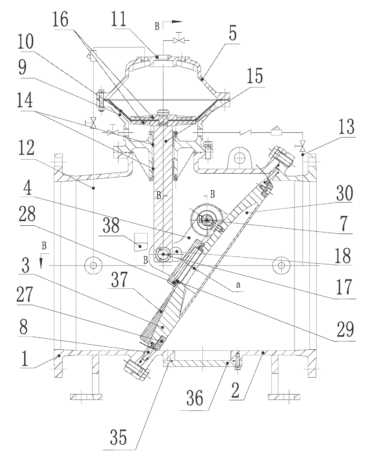
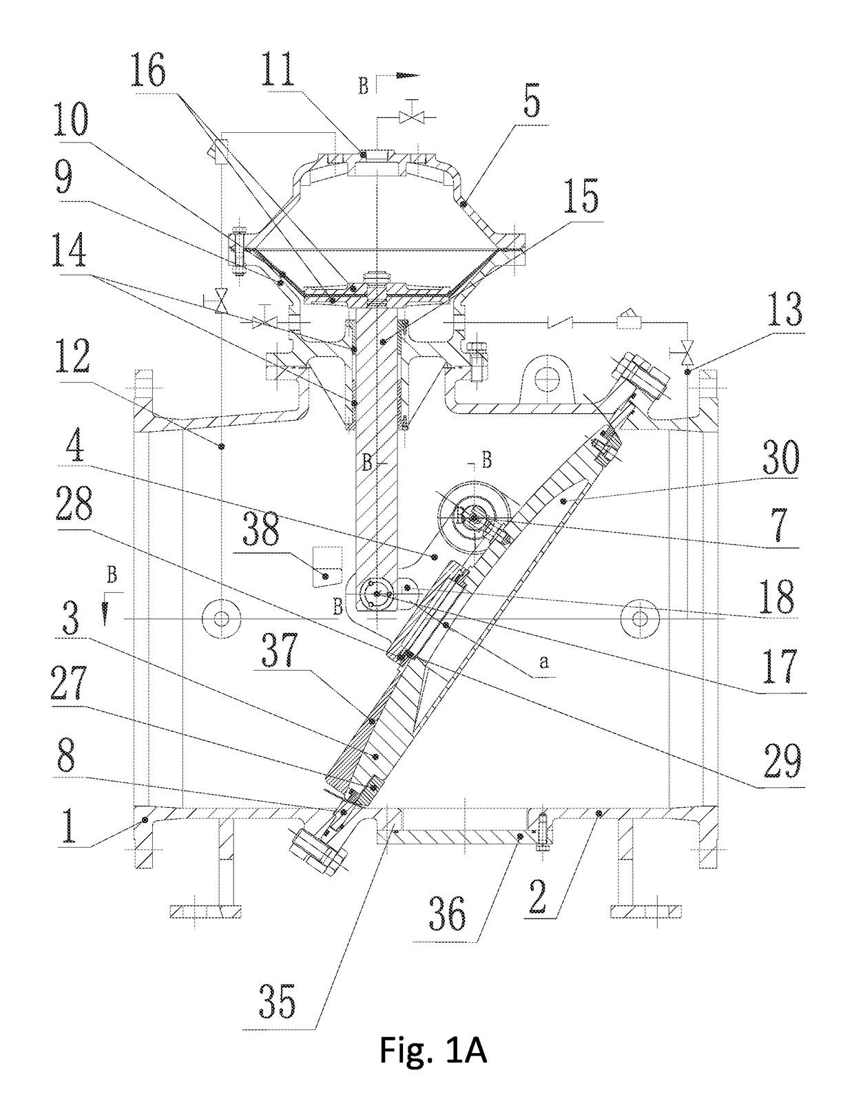
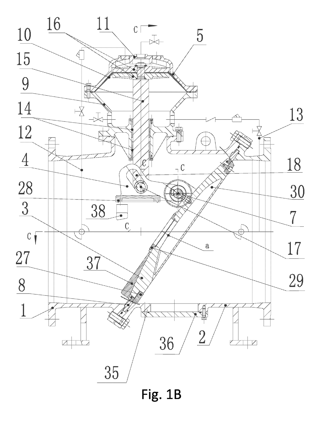
[0038]FIGS. 1A-1C are side sectional diagrams of a diaphragm control slider type tilting disc check valve according to a preferred embodiment of the invention showing diaphragm and valve parts in moved positions, FIGS. 2A-2B are end sectional view diagrams of a diaphragm control slider type tilting disc check valve according to a preferred embodiment of the invention, showing diaphragm and valve parts in moved positions, FIG 2C is an end exterior view of a diaphragm control slider type tilting disc check valve according to an embodiment of the invention, FIGS. 3A-3B are side sectional view diagrams of a diaphragm control connecting rod type tilting disc check valve according to a preferred embodiment of the invention, showing diaphragm and valve parts in moved positions, and FIG. 4 is an ex...


PUM


Abstract

The invention discloses a tilting disc check valve, which includes a left valve body (1), a right valve body (2), a large valve plate (3), a small valve plate (4) and a diaphragm control group (5), wherein the left valve body (1) and the right valve body (2) are butted into a whole through oblique openings; the oblique openings are inclined in a manner that upper parts are inclined towards the right valve body (2); the diaphragm control group (5) is arranged on the left valve body (1); the large valve plate (3) is arranged along the oblique openings; the large valve plate (3) is positioned in a valve cavity formed by the left valve body (1) and the right valve body (2); the large valve plate (3) is suspended on shaft holes of the left valve body (3) through valve shafts (6); the small valve plate (4) is connected with the diaphragm control group (5); and the small valve plate (4) is mounted at a slow closing valve port of the large valve plate (3) through a small valve plate pin shaft (7). According to the tilting disc check valve, a two-stage valve closing process where the large valve plate is quickly closed and the small valve plate at a drain hole of the large valve plate is slowly closed within adjustable time can be implemented, and the aims of reducing backflow of a water body and eliminating pump starting and stopping water hammer are fulfilled.

Description

TECHNICAL FIELD OF THE INVENTION[0001]The invention relates to the technical field of check valves, and in particular to a diaphragm type slider control tilting disc check valve mounted at a water outlet of a water pump.BACKGROUND OF THE INVENTION[0002]A check valve is a group arranged in a pipeline to make a medium directionally to flow without backflow, and is used for various pipe networks more and more widely. At present, a check valve mounted at a water outlet of a water pump is capable of automatically realizing pump starting when valve is closed and two-stage closing without any other additional device has many problems in terms of structure and use.[0003]① A slow closing small valve plate (or called a slow closing cam) is connected with a valve rod through a hinge (or a chain plate) with a sliding chute, there is a free travel, the valve rod cannot completely control the position of the slow closing small valve plate, and in a running process of the valve, the slow closing s...

Claims


Application Information

Patent Timeline
Patent Type & Authority Patents(United States)
IPC IPC(8): F16K15/18F04B53/00F04B53/10F16K31/126F16K1/20F16K47/02F16K39/02
CPCF16K15/181F04B53/001F04B53/102F04B53/1087F16K1/20F16K31/1266F16K39/024F16K39/028F16K47/023F16K1/2021Y10T137/7841F16K15/1821
Inventor HUANG, JINGLUO, JIANQUNGUI, XINCHUNTANG, AIHUAYIN, JIANGUODONG, ZHEN
Owner ZHUZHOU SOUTHERN VALVE
Why Eureka
Try Eureka