Band saw blade

a band saw blade and band saw technology, applied in the field of band saw blades, can solve the problems of relatively high impact cutting force imparted to the cutting teeth, limited feed force and can vary, and the band saw blades used in such applications, and achieve the effects of robust tooth form, and improving the resistance to premature tooth stripping and chipping

Active Publication Date: 2018-10-30
BLACK & DECKER INC
View PDF24 Cites 5 Cited by
  • Summary
  • Abstract
  • Description
  • Claims
  • Application Information

AI Technical Summary

Benefits of technology

[0019]One advantage of the present invention is that the first primary clearance angles of the heavy set teeth are less than or equal to about 20°. This feature provides relatively large included angles between the primary clearance angles and rake faces of the heavy set teeth, and thereby provides a robust tooth form, including a relatively long bimetal weld interface, in the cutting teeth that encounter the most substantial cutting forces. This, in turn, provides significantly improved resistance to the premature tooth stripping and chipping encountered in prior art band saw blades. Yet another advantage of the present invention is that the second primary clearance angles of the unset and light set teeth are less than or equal to about 25°. Although greater than the first primary clearance angles, the second primary clearance angles are nevertheless relatively shallow, providing for relatively large included angles between the primary clearance angles and rake faces of the unset and light set teeth, and thereby providing a robust tooth form, including a relatively long bimetal weld interface. This feature further contributes to providing significantly improved resistance to the premature tooth stripping and chipping encountered in prior art band saw blades.
[0020]Another advantage of the present invention is that each unset and light set tooth defines a greater gullet area than a respective heavy set tooth and / or a finer pitch than the respective heavy set tooth. The unset and light set teeth in each pitch pattern thus define a greater gullet capacity than the heavy set teeth in the pitch pattern, thereby providing substantially improved resistance to gullet overfill, and substantially obviating the associated high manual feed forces, reduced feed rates, blade stalling, and / or crooked cutting encountered in prior art band saw blades. Yet another advantage of this feature is that it can allow for significantly faster cutting times in comparison to prior art band saw blades, particularly when cutting structural shapes, such as structural, roll-formed metal work pieces.
[0021]A further advantage of embodiments of the band saw blades of the present invention is that each tooth defines a positive rake angle within the range of about 3° to about 10°, and which is preferably greater than about 4°, is more preferably greater than about 6°, and is even more preferably greater than about 7°. The relatively large included angles resulting from the shallow primary clearance angles allow for such aggressive rake angles, without significantly impacting the robustness of the tooth form, and thus without significantly impacting the resistance of the teeth to the stripping and chipping encountered in prior art band saw blades. On the other hand, the relatively aggressive rake angles contribute to achieving faster cutting times in comparison to prior art band saw blades, particularly in manual pull-down band saws, such as when cutting structural, metal work pieces.
[0022]Accordingly, another advantage of the band saw blades of the present invention is that they balance toughness against cutting speed, where toughness is achieved with relatively shallow primary clearance angles, and cutting speed is achieved with increased overall gullet capacity of the unset and light set teeth as compared to the heavy set teeth, and with aggressive rake angles for all teeth or substantially all teeth.
[0023]Another advantage of some embodiments of the present invention is that the light and heavy set teeth are set to a lesser degree than the light and heavy set teeth, respectively, of prior art band saw blades. More specifically, each light set tooth defines a set within the range of about 0.005 inch to about 0.007 inch, and each heavy set tooth defines a set within the range of about 0.008 inch to about 0.010 inch. The lesser degree of set imparts a relatively narrow kerf width to the work pieces in comparison to prior art band saw blades, which, in turn, contributes to more efficient cutting and significantly faster cutting times in comparison to prior art band saw blades, particularly when cutting structural shapes, such as structural, roll-formed metal work pieces.
[0024]Other objects and advantages of the present invention, and / or of the currently preferred embodiments thereof, will become more readily apparent in view of the following detailed

Problems solved by technology

As a result, the feed force is limited and can vary depending on the physical strength and ability of the operator.
Due to the relatively uncontrolled nature of the feed force in manual pull-down band saws, relatively high impact cutting forces can be imparted to the cutting teeth, particularly when cutting metal, structural work pieces.
As a result, a primary failure mode of band saw blades used in such applications is tooth damage due to chipping at the tool steel tips and / or stripping of the teeth away from the band at the bi-metal weld region or interface.
One of the drawbacks of prior art band saw blades used in such applications is that the blades fail prematurely, particularly as a result of the above-mentioned tooth chipping and / or stripping, and therefore the blades do not provide as long a blade life as desired.
Another drawback is that the band saw blades do not use the manually-supplied feed forces as efficiently as desired, and as a result, the time required to cut through work pieces can be longer than desired.
The present inventor has determined that these methodologies have achieved varying and limited levels of effectiveness.
The first methodology can cause the cutting to be less efficient than desired while allowing for only relatively minimal gains in resisting tooth strippage.
This can reduce the rate at which the band saw is fed into the work piece, can cause the blade to stall and / or can lead to crooked cutting.

Method used


Image

  • Band saw blade
  • Band saw blade
  • Band saw blade

Examples


Embodiment Construction

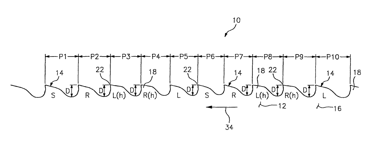
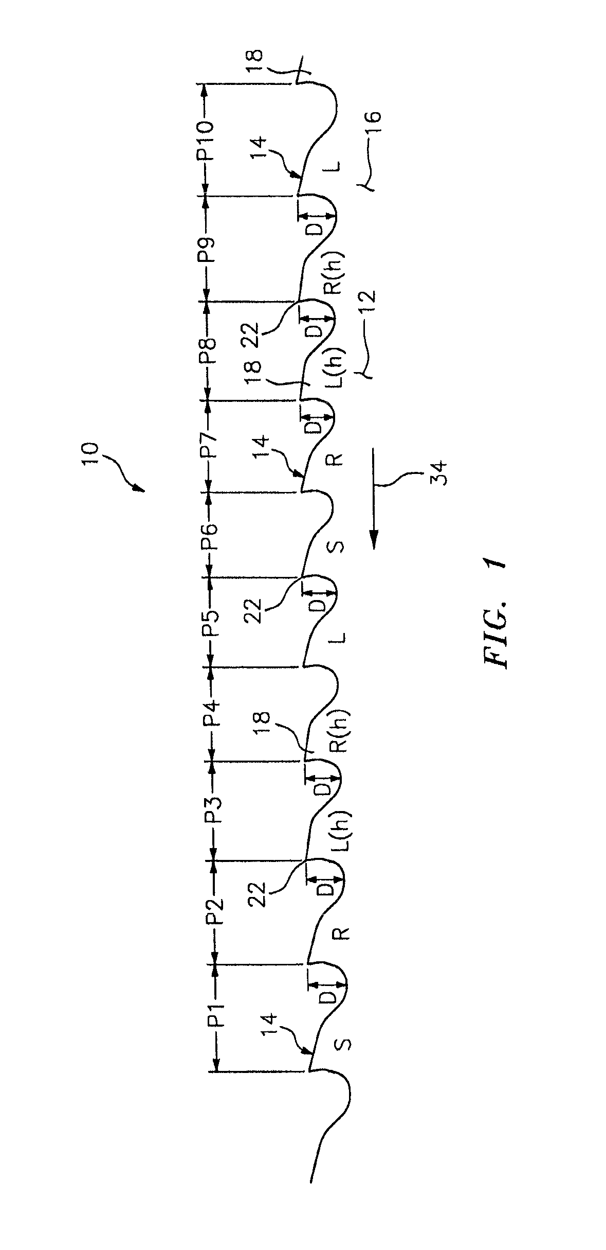
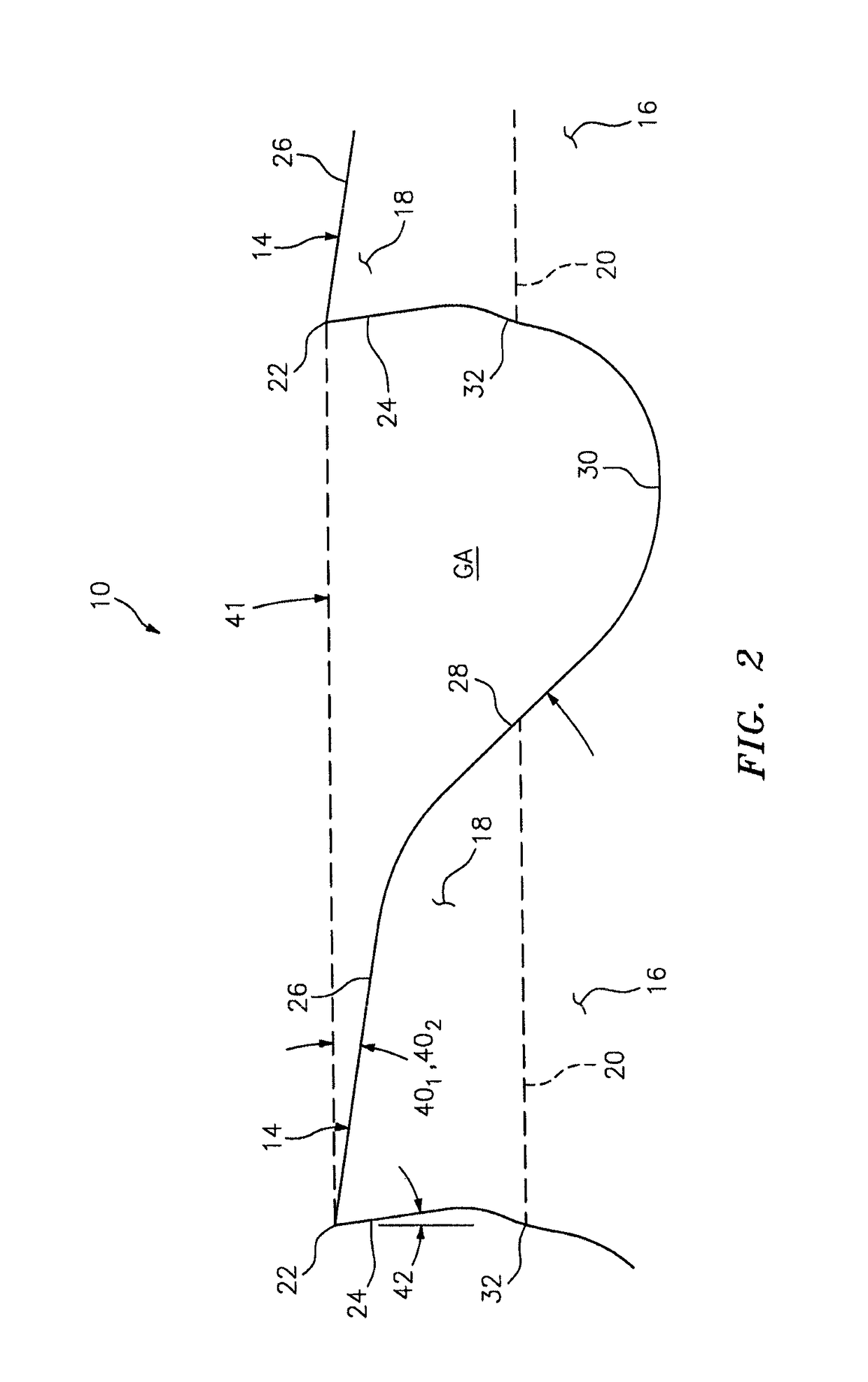
[0032]In FIGS. 1 and 2, a band saw blade embodying the present invention is indicated generally by the reference numeral 10. The bade saw blade 10 comprises a blade body 12 and a cutting edge defined by a plurality of cutting teeth 14. In the illustrated embodiment, the band saw blade 10 is a bimetal blade including a relatively flexible spring steel backing 16 welded to a tool steel strip defining tool steel tips 18 on the teeth. As shown typically in broken lines in FIG. 2, a weld line 20 is formed between each tool steel cutting tip 18 and the spring steel backing 16.

[0033]As also shown typically in FIG. 2, each tooth includes a cutting tip 22, a rake face 24 located on one side of the tip, a primary clearance surface 26 located on an opposite side of the tip relative to the rake face, a secondary clearance surface 28 located on an opposite side of the primary clearance surface relative to the tip, a gullet 30 located on an opposite side of the secondary clearance surface 28 rela...


PUM


Abstract

A bimetal band saw blade has a cutting edge with a plurality of cutting teeth defining repeating, variable pitch patterns and variable set patterns within pitch patterns. Each relatively heavy set tooth defines a first primary clearance angle, and each unset and relatively light set tooth defines a second primary clearance angle. Each first primary clearance angle is less than or equal to about 20°, each second primary clearance angle is less than or equal to about 25°, and each first primary clearance angle is within the range of about 4° to about 6° less than each second primary clearance angle. Each unset or light set tooth defines a greater gullet area than a respective heavy set tooth and / or a finer pitch than the respective heavy set tooth. Each tooth defines a positive rake angle within the range of about 3° to about 10°.

Description

FIELD OF THE INVENTION[0001]The present invention relates to saw blades, and more particularly, to band saw blades where the cutting teeth define variable clearance angles and variable set patterns within variable pitch patterns.BACKGROUND INFORMATION[0002]In a typical manual “pull-down” band saw the force at which the band saw blade is fed into the work piece is not mechanically controlled, but rather is provided manually by the operator. As a result, the feed force is limited and can vary depending on the physical strength and ability of the operator. Such pull-down band saws can be used to cut metal work pieces including, for example, roll formed, structural shapes, such as metal pipes, fence posts, and other metal work pieces defining unique or odd shaped profiles. The band saw blades used for such applications are typically bi-metal with flexible, spring steel backings, and cutting teeth with tool steel tips that are welded to the spring steel backings. Due to the relatively un...

Claims


Application Information

Patent Timeline
Patent Type & Authority Patents(United States)
IPC IPC(8): B23D61/12
CPCB23D61/12B23D61/123B23D61/121
Inventor HUNTER, MATTHEWCRANNA, MARK T
Owner BLACK & DECKER INC
Why Eureka
Try Eureka