Remote gas leakage detection systems using mid-infrared laser

a gas leakage detection and laser technology, applied in the field of gas leakage detection, can solve the problems of aging gas delivery infrastructure, high cost, and inconvenient operation, and achieve the effects of improving accuracy, reducing labor intensity, and improving accuracy

Inactive Publication Date: 2018-10-30
AURORA INNOVATIVE TECH LLC
View PDF6 Cites 20 Cited by
  • Summary
  • Abstract
  • Description
  • Claims
  • Application Information

AI Technical Summary

Problems solved by technology

However, at the same time, gas delivery infrastructure is aging.
However, these detection methods are often unreliable, inefficient, and expensive.

Method used


Image

  • Remote gas leakage detection systems using mid-infrared laser
  • Remote gas leakage detection systems using mid-infrared laser
  • Remote gas leakage detection systems using mid-infrared laser

Examples


Embodiment Construction

[0010]The figures and the following description relate to preferred embodiments by way of illustration only. It should be noted that from the following discussion, alternative embodiments of the structures and methods disclosed herein will be readily recognized as viable alternatives that may be employed without departing from the principles of what is claimed.

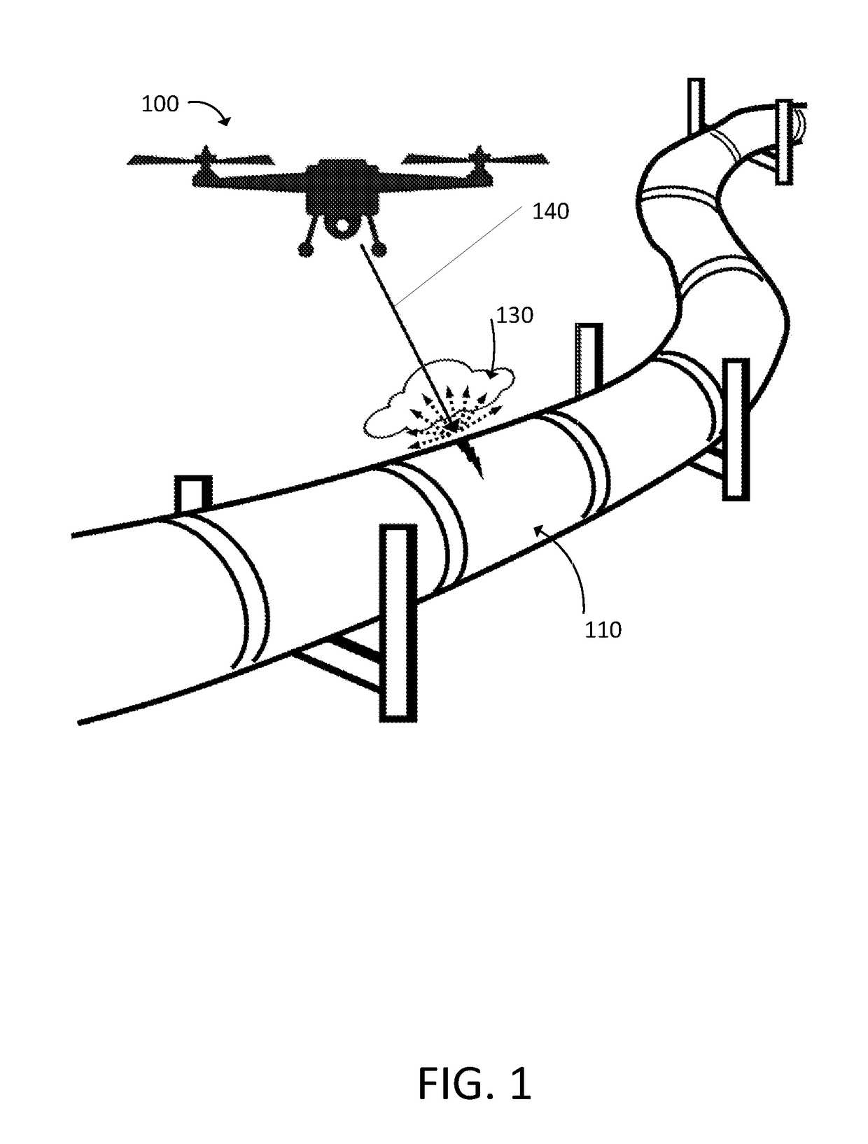
[0011]FIG. 1 illustrates an example environment in which an example gas detection system 100 operates. The example gas detection system 100 can remotely detect whether a gas pipe 110 has any gas leakage. In one example, the gas detection system can remotely detect gas leakage at a range of up to 50 meters. The detection system 100 detects gas leakage by detecting whether there is leaked gas in an area 130 that is between the detection system 100 and the gas pipe 110. As further described below, the detection system 100 projects one or more light beams 140 towards the gas pipe 110 while traversing along the gas pipe 110. The li...


PUM

PropertyMeasurementUnit
mid-IR wavelength rangeaaaaaaaaaa
frequencyaaaaaaaaaa
wavelengthsaaaaaaaaaa

Abstract

A system remotely detects a gas leakage from a target in an area. The gas detection system includes two light sources: a mid-infrared (mid-IR) laser for detecting absorbance of the gas in the area, and a visible laser for detecting a pathlength of the mid-IR laser. The absorption is determined based on the relative amplitude difference of the emitted and reflected mid-IR light beams. The mid-IR laser may use wavelength modulation techniques to improve the absorption determination. The pathlength is determined by comparing a phase between the emitted visible light beam and the measured visible light beam. The gas detection system calculates a concentration of the gas in the area using the determined absorption and pathlength. The gas detection system may be attached to an unmanned aerial vehicle.

Description

BACKGROUND OF THE INVENTION1. Field of the Invention[0001]This description relates generally to detection of gas leakage, and more specifically detection of gas leakage using mid-infrared laser.2. Description of the Related Art[0002]Natural gas consumption in the US is expected to increase rapidly. However, at the same time, gas delivery infrastructure is aging. Accordingly, reliable and timely detection of natural gas leakage is critical to ensure the gas delivery infrastructure's reliability. Conventional non-optical methods that detect natural gas leakage are based on various mechanisms such as manual inspection, acoustic monitoring; gas sampling; soil monitoring; flow monitoring; and software based dynamic modeling. However, these detection methods are often unreliable, inefficient, and expensive.SUMMARY OF THE INVENTION[0003]Described is a gas detection system for remotely detecting gas leakage from a target in an area. The gas detection system uses mid-infrared (mid-IR) laser ...

Claims


Application Information

Patent Timeline
Patent Type & Authority Patents(United States)
IPC IPC(8): G01J5/02G01N21/39B64C39/02G01N21/61G01N33/00G01N21/3504
CPCG01N21/3504G01N21/39B64C39/02G01N21/61G01N33/0027G01N2021/1795G01N2021/3513G01N2021/399G01M3/38B64C39/024B64U2101/30G01M3/00
Inventor LI, JIEBOGUO, XUNMINZHAO, WANYI
Owner AURORA INNOVATIVE TECH LLC
Why Eureka
Try Eureka