Heat-pump-type vehicular air-conditioning system

a vehicular air conditioner and heat pump technology, applied in refrigeration components, transportation and packaging, light and heating apparatus, etc., can solve problems such as heating operation, achieve efficient heating operation, enhance the capability of heating operation, and cool operation and heating operation

Inactive Publication Date: 2018-11-06
MITSUBISHI HEAVY IND THERMAL SYST
View PDF94 Cites 10 Cited by
  • Summary
  • Abstract
  • Description
  • Claims
  • Application Information

AI Technical Summary

Benefits of technology

[0023]According to the present invention, a system having three heat exchangers is configured, with the onboard condenser provided within the HVAC unit, the first circuit having the second decompression unit, and the second circuit having the solenoid valve in addition to the cooling refrigerant circuit that is substantially equivalent to the cooling refrigerant circuit of a current system. While in a cooling mode, two heat exchangers are functioning, namely the onboard evaporator and the vehicle-mounted external heat exchanger (functioning as a condenser). Likewise, while in a heating mode, two heat exchangers are functioning, namely the onboard condenser and the vehicle-mounted external heat exchanger (functioning as an evaporator). Thus, cooling operation and heating operation are both enabled without heat radiation loss and reheating loss. As such, the cooling operation and the heating operation are performed efficiently at the maximum capability commensurate with the workload of the electric compressor, thus enabling the capabilities thereof to be enhanced. Also, the system is configured to use three heat exchangers, which enables simplification of the configuration, miniaturization, and cost reduction. In addition, while in the heating mode, upon frost formation on the vehicle-mounted external heat exchanger, effective defrosting is made possible by switching to the cooling circuit and directly guiding the hot gas to the vehicle-mounted external heat exchanger. As such, the defrosting time may be reduced and the range of outside air temperatures in which defrosting is possible may be expanded.

Problems solved by technology

A vehicular air conditioning system used in an EV, a hybrid electric vehicle (HEV), a plug-in hybrid electric vehicle (PHEV), and the like is unable to perform a heating operation using combustion exhaust heat of engine cooling water and the like.

Method used


Image

  • Heat-pump-type vehicular air-conditioning system
  • Heat-pump-type vehicular air-conditioning system
  • Heat-pump-type vehicular air-conditioning system

Examples


first embodiment

[0037]A first embodiment of the present invention is described below, with reference to FIGS. 1 through 7.

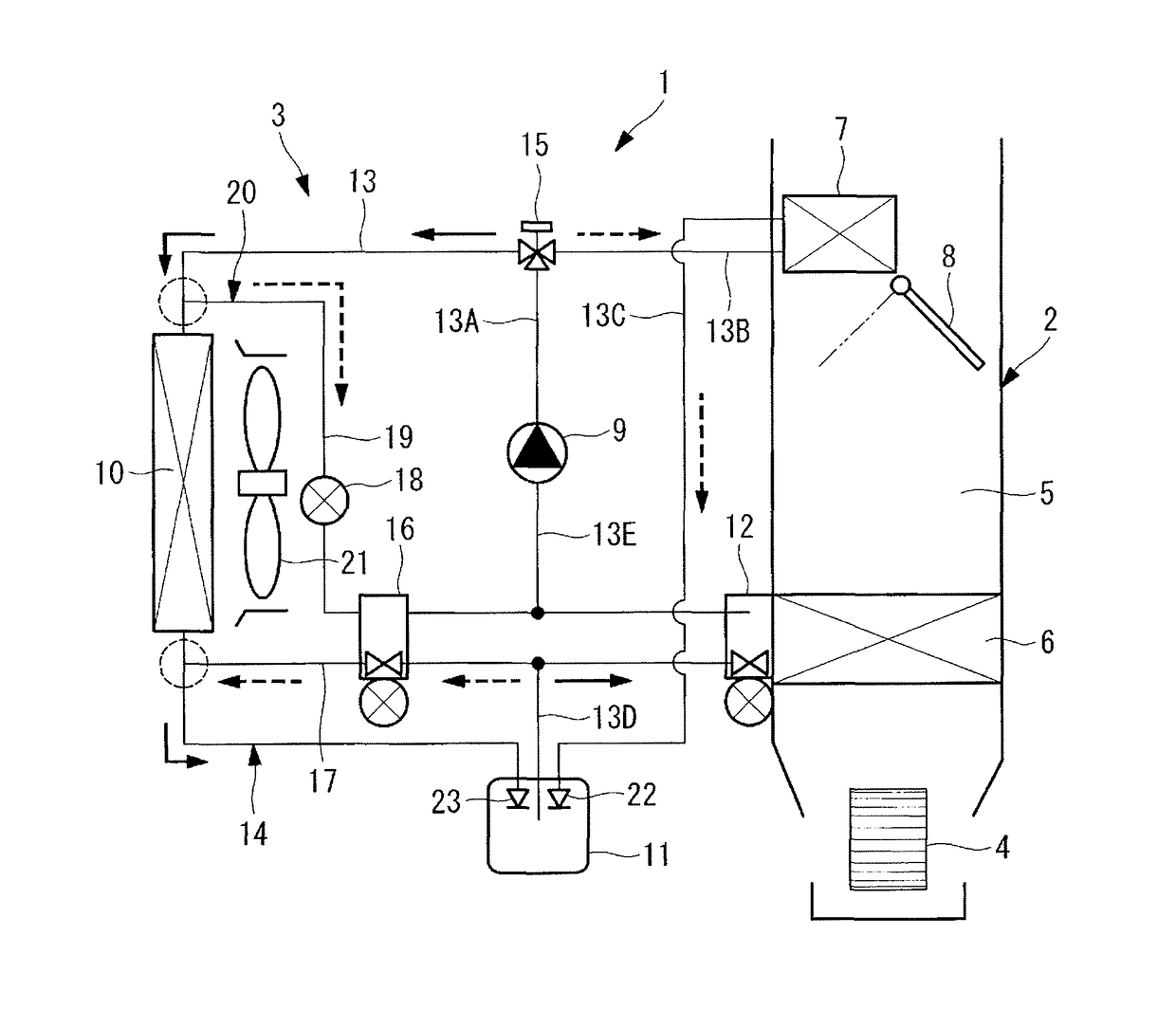
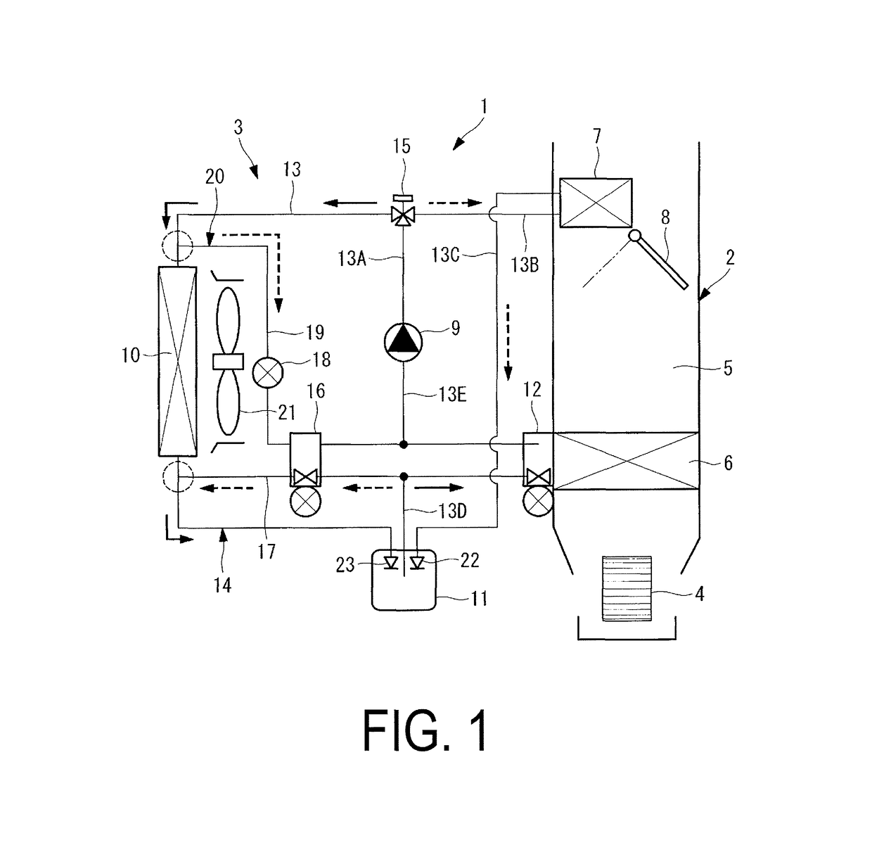
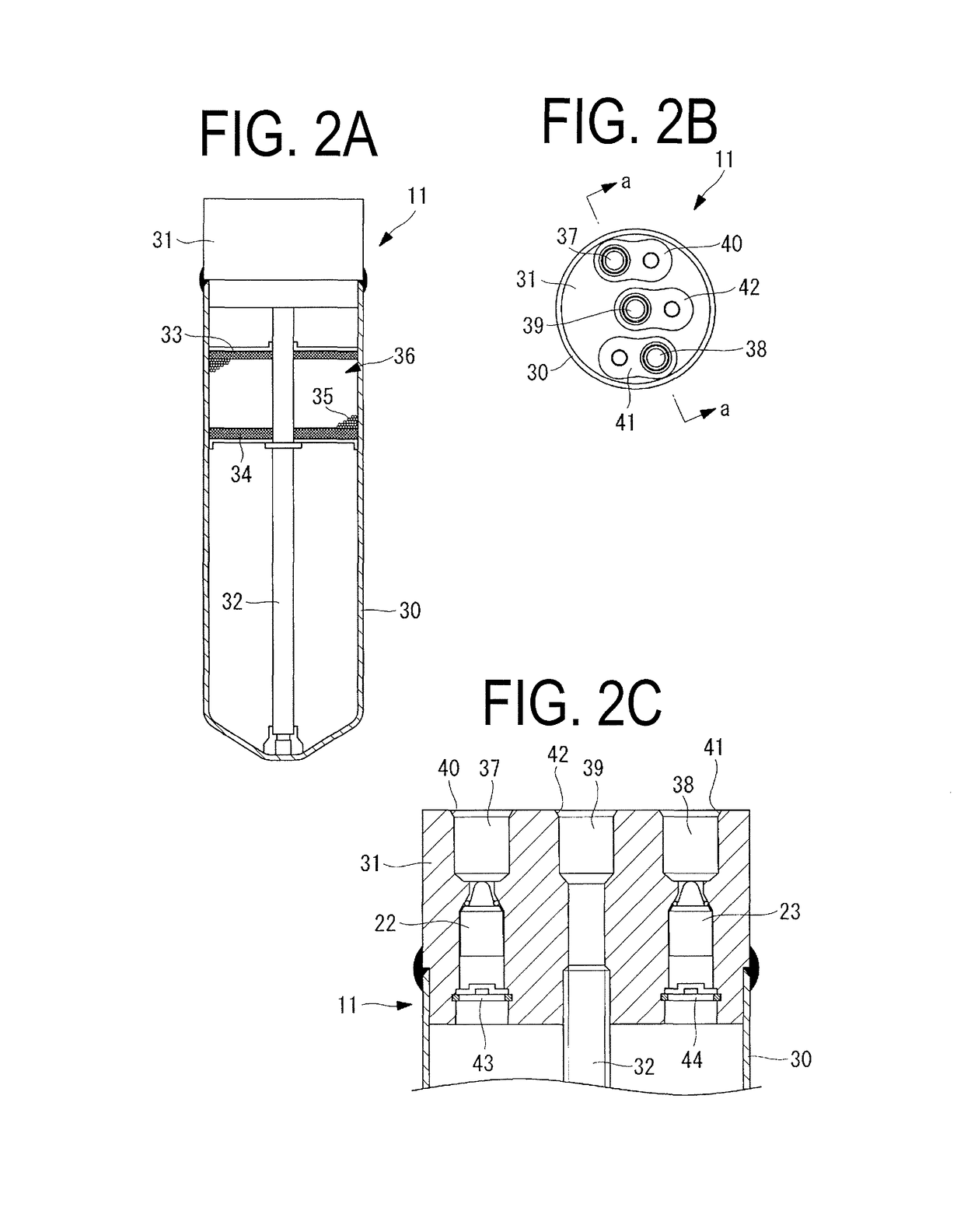
[0038]FIG. 1 is a refrigerant circuit diagram illustrating a heat-pump-type vehicular air-conditioning system pertaining to the first embodiment of the present invention. FIGS. 2A, 2B and 2C are configuration diagrams of a receiver incorporated into the system. FIG. 3 is a configuration diagram illustrating a temperature-driven automatic expansion valve equipped with a solenoid valve and also incorporated into the system.

[0039]A heat-pump-type vehicular air-conditioning system 1 pertaining to the present embodiment includes a heating ventilation and air conditioning unit (HVAC unit) 2 and a refrigerant circuit 3 capable of heating and cooling, being a heat-pump-type circuit.

[0040]The HVAC unit 2 includes a blower 4 switching between drawing one of outside air and inside air from inside a vehicle cabin, and blowing the air to a downstream side, an onboard evaporator 6 disposed on...

second embodiment

[0077]Next, a second embodiment of the present invention is described with reference to FIGS. 8 through 12.

[0078]The present embodiment differs from the above-described first embodiment only in that a second decompression unit 16A is equipped with a check valve. Other points of the second embodiment are similar to the first embodiment, and the description thereof is therefore omitted.

[0079]In the above-described first embodiment, the second decompression unit 16 is provided with the on-off valve function by using the solenoid valve-equipped temperature-driven automatic expansion valve 50. However, in the present embodiment, the second decompression unit 16A provided in the first circuit 17, which is for heating, is configured by removing the solenoid valve 51 from the solenoid valve-equipped temperature-driven automatic expansion valve 50 illustrated in FIG. 3, leaving a temperature-driven automatic expansion valve that is only the temperature-driven automatic expansion valve 52, an...


PUM


Abstract

A heat-pump-type vehicular air-conditioning that includes a cooling refrigerant circuit. The circuit has a base for connecting an onboard condenser provided on the downstream side of an onboard evaporator inside an HVAC unit. The circuit includes a second decompression unit between the outlet side of a receiver and one end side of a vehicle-mounted external heat exchanger. Also included is a second circuit having a solenoid valve opened during heating between the other end side of the vehicle-mounted external heat exchanger and the intake circuit of an electric compressor. The vehicular air-conditioning system being provided with a heating refrigerant circuit in which the electric compressor, a switching unit, the onboard condenser, the receiver, the first circuit, the vehicle-mounted external heat exchanger, and the second circuit are connected in the stated order.

Description

TECHNICAL FIELD[0001]The present invention pertains to a heat-pump-type vehicular air-conditioning system applicable to air conditioning in an electric vehicle (hereinafter, EV) or the like.BACKGROUND ART[0002]A vehicular air conditioning system used in an EV, a hybrid electric vehicle (HEV), a plug-in hybrid electric vehicle (PHEV), and the like is unable to perform a heating operation using combustion exhaust heat of engine cooling water and the like. As such, a heat-pump-type air-conditioning system using an electric compressor is being considered. However, in a situation involving a reverse-type heat pump, various pipes and heat exchangers such as evaporators, condensers, and the like making up a refrigerant circuit must be able to operate jointly under different pressure conditions for cooling operation and heating operation. Thus, a current vehicular air conditioning system applicable to an engine-driven vehicle must be completely modified.[0003]As such, a heat-pump-type vehic...

Claims


Application Information

Patent Timeline
Patent Type & Authority Patents(United States)
IPC IPC(8): B60H1/00B60H1/22F25B13/00F25B41/06
CPCB60H1/22B60H1/00899B60H1/00921F25B13/00F25B41/062F25B2400/16B60H2001/00928F25B2313/02342F25B2313/02732F25B2313/02791B60H2001/00961F25B41/325F25B41/335
Inventor KOHIGASHI, HIROTSUGUNAKAGAWA, NOBUYA
Owner MITSUBISHI HEAVY IND THERMAL SYST
Why Eureka
Try Eureka