Swather with a single or double raking frame, device for arms with wheel rakes and corresponding wheel rakes

a technology of raking frame and raking arm, which is applied in the field of raking frame, can solve the problems of affecting the safety of operators and, generally, of all persons nearby, and the heavy weight of the raking frame, and achieves the effects of reducing the safety of operators, and reducing the risk of accidents

Active Publication Date: 2018-11-13
ENOAGRI ROSSI
View PDF29 Cites 0 Cited by
  • Summary
  • Abstract
  • Description
  • Claims
  • Application Information

AI Technical Summary

Benefits of technology

[0027]The Applicant has set itself the aim of overcoming the different problems mentioned above by means of technical solutions that, in the whole, allow manufacturing a swather with very high efficiency.
[0040]When the arm is then to be opened again, the operator can operate the actuating means directly from its driving position, in order to release the cylinder from its seat in the circular hole of the second strip, and hence can allow the arm with wheel rakes to open to the working position.
[0041]In accordance with the present exemplary embodiment, it is also possible to connect the control of the opening of the aim with wheel rakes with the control of the small cylinder release, so as to automatically release the small cylinder when commanding the opening of the arm, thereby avoiding possible damages to the equipment.
[0042]As to the third technical problem, the Applicant has set itself the aim of obviating the drawback of having different wheel rakes for each swather arm, by providing a wheel rake with a new design, which is simple to build and is reversible, that is, it can be indifferently mounted on both arms or sides of the swather.
[0045]Thanks to such a configuration, a perfectly flat structure is achieved for the wheel rake, so that the latter can be mounted without any difficulty on both the left side and the right side of any swather.
[0051]Thus, it is an object of the present invention to solve the general technical problem described above by means of a plurality of technical solutions that, alone and / or in combination, are such that they make the possibility of working wider and wider cultivated areas in more and more reduced working times more and more effective.

Problems solved by technology

For instance, the economic need to work wider and wider cultivated areas in reduced working times has led to swathers with very long arms with the wheel rakes: however, for that reason, such arms become very heavy and complex to be moved.
A first technical problem of the known swathers is that the excessive arm lengths, in combination with the often rough surfaces of the fields, has the consequence that the arms, in use, can be subjected to stresses and can develop cracks and subsequently fractures, which are a damage from the economic standpoint and are potentially dangerous for the safety of the operators and, generally, of all persons nearby.
A second technical problem, related to the first one, is that, at present, the arms are locked in their closed position by mechanically securing them to said first horizontal bar, for instance by means of elongated rigid elements such as metal rods, tube pieces and the like, which are provided with eyelets at their ends and are to be bolted to both the arms and the first horizontal bar.
Already from this short description of the operation, one can understand that the same cannot be carried out easily and in short times, and moreover that it can also give rise to the risk that the operator hurts himself / herself during the arm alignment and securing.
Such a situation entails the further technical problem, always related to the presence of longer and longer arms, that, both during swather transportation and during some phases of use, such as for instance direction reversal in narrow areas, displacement from one field to another, and so on, it is necessary to bring the arms to their closed position and also to lock them in such position, in order to prevent the length and the weight of the arms from overcoming the resistance of the actuating means, for instance hydraulic cylinders arranged to operate the arms, thereby causing displacement of the arms from the closed to the open position, this being likely to result in damages to the arms, to the swather itself or to structures or to other means nearby or even to people.
A third, more general technical problem is related to the wheel rakes arranged along the swather arms.
In general, the Applicant has realised that the prior art is not able to effectively solve the most general technical problem of making the swathers more and more effective in view of the economic need to work wider and wider cultivated areas in more and more reduced working times.
The Applicant has also realised that the prior art is not able to solve the several technical problems preventing the attainment of swathers meeting the actual needs of the operators.

Method used


Image

  • Swather with a single or double raking frame, device for arms with wheel rakes and corresponding wheel rakes
  • Swather with a single or double raking frame, device for arms with wheel rakes and corresponding wheel rakes
  • Swather with a single or double raking frame, device for arms with wheel rakes and corresponding wheel rakes

Examples


third embodiment

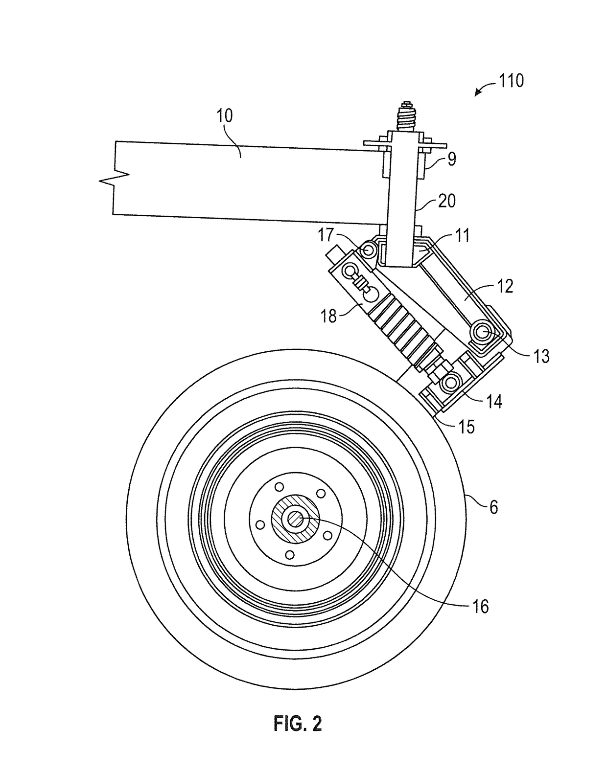
[0063]FIG. 7 is a perspective view of a flanged wheel rake for swathers, made in accordance with the present invention.

DESCRIPTION OF PREFERRED EMBODIMENTS

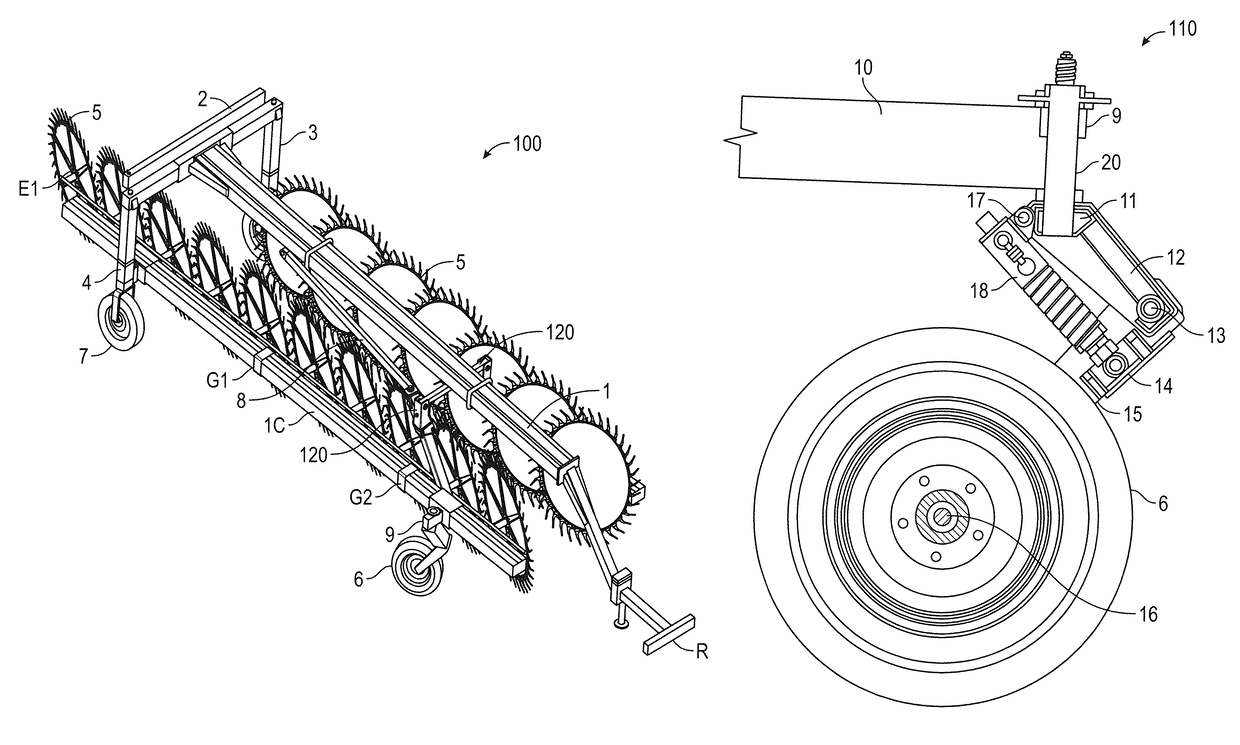
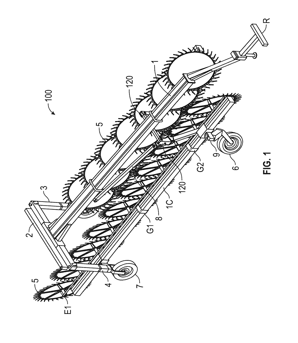
[0064]Referring to FIG. 1, a swather 100 according to the present invention is for instance a swather with Y-shaped configuration, that is, it has two arms with wheel rakes 5. Only one arm, denoted by reference numeral 10, is shown for the sake of convenience of description.

[0065]In the embodiment shown by way of example the arms have different lengths. The first arm 10 is pivotally connected at one end on a vertical member 3, and the second arm is pivotally connected, at a distance from one end thereof, on a second vertical member 4 supported by a horizontal support bar 2.

[0066]Thanks to such a structure, when the arms are opened to a working position by means of an actuating device 8, one end E1 of the first arm 10 covers the corresponding end (not shown) of the second arm, so that wheel rakes 5 of both arms entirely cover the s...


PUM


Abstract

A swather having a horizontal bar with a device for connection to a towing vehicle and a generally horizontal bar, transverse to the first one, each end of which is associated with a generally vertical member bearing a wheel. The assembly of the transverse bar and the vertical members being associated with generally horizontal long arms directed toward a first end of the first horizontal bar and pivotally connected to the transverse bar or the vertical members, so that the arms, when extended to a working position, provide a V-shaped or Y-shaped configuration. Each arm is equipped with a pivoting wheel with tire at its end remote from the transverse bar, or distal end, and with wheel rakes. At least the pivoting wheels with tires are equipped with shock absorbing means capable of attenuating impulsive loads due to impact of the wheels against ground irregularities.

Description

TECHNICAL FIELD[0001]The present invention generally relates to a swather with a single or double raking frame.[0002]More particularly, the present invention relates to a swather having arms with wheel rakes and equipped with wheels with tyres.[0003]The present invention also relates to a device usable for locking the arms with wheel rakes and to wheel rakes usable in the swather and the device.PRIOR ART[0004]Swathers and their use are known in the art.[0005]As known, a swather is a product or system, which generally is towed by a towing vehicle driven by an operator and is used in agriculture for collecting previously cut grass, hay, specific fodders or the like, into windrows orderly arranged on the ground.[0006]A prior art swather generally includes a first horizontal bar, having at a first end a device for connection to a towing vehicle, generally a tractor, and having at the opposite end a generally horizontal second bar, transverse to the first one, of which the ends are each ...

Claims


Application Information

Patent Timeline
Patent Type & Authority Patents(United States)
IPC IPC(8): A01D57/28A01D80/00A01D57/12A01D78/14
CPCA01D57/28A01D57/12A01D80/00A01D78/146A01D78/14
Inventor GIOVANNINI, ADELMO
Owner ENOAGRI ROSSI
Why Eureka
Try Eureka