
Endovascular permanent heart assist device

a permanent, heart-related technology, applied in the field of new-generation small heart-related assist devices, can solve the problems of heart failure, annoying compressed air systems, difficult to find a donor for a heart transplant, etc., and achieve the effect of avoiding extra metal load in the patient's body and easy updating and renewing them every year

Active Publication Date: 2018-11-13
BULENT ORAN +2
View PDF24 Cites 3 Cited by
  • Summary
  • Abstract
  • Description
  • Claims
  • Application Information

AI Technical Summary

Benefits of technology

This patent is for a heart assist device that can be placed inside large arteries to help patients with severe heart failure. The device has a rotor with blades that rotate to push blood through the arteries. The device can be powered using three-phase AC electric voltage, which is transmitted to the device through separate wireless links. The device has a unique design that reduces energy consumption and allows for longer battery life. The rotor rotates during the heart's contraction and stops or slows down during relaxation. Overall, this technology represents a new and innovative solution for heart failure treatment.

Problems solved by technology

Uninterruptible three-phase electrical power transmission, required to run this asynchronous three-phase motor, is provided from outside the body wirelessly.
Since finding a donor for a heart transplant is not very easy, heart assist devices kept ready for emergency use have become life-saving.
In addition, some heart diseases may lead to heart failure even in newborn infants.
Compressed air systems were annoying as they run loudly.
Because the efficiency of the engine was low and the engine volume was large in electric motor systems, it was a problem to install it into the patients.
Moreover, considering them as high-energy-consuming systems, they significantly restricted the ability of the patients to move.

Method used


Image

  • Endovascular permanent heart assist device
  • Endovascular permanent heart assist device
  • Endovascular permanent heart assist device

Examples


Embodiment Construction

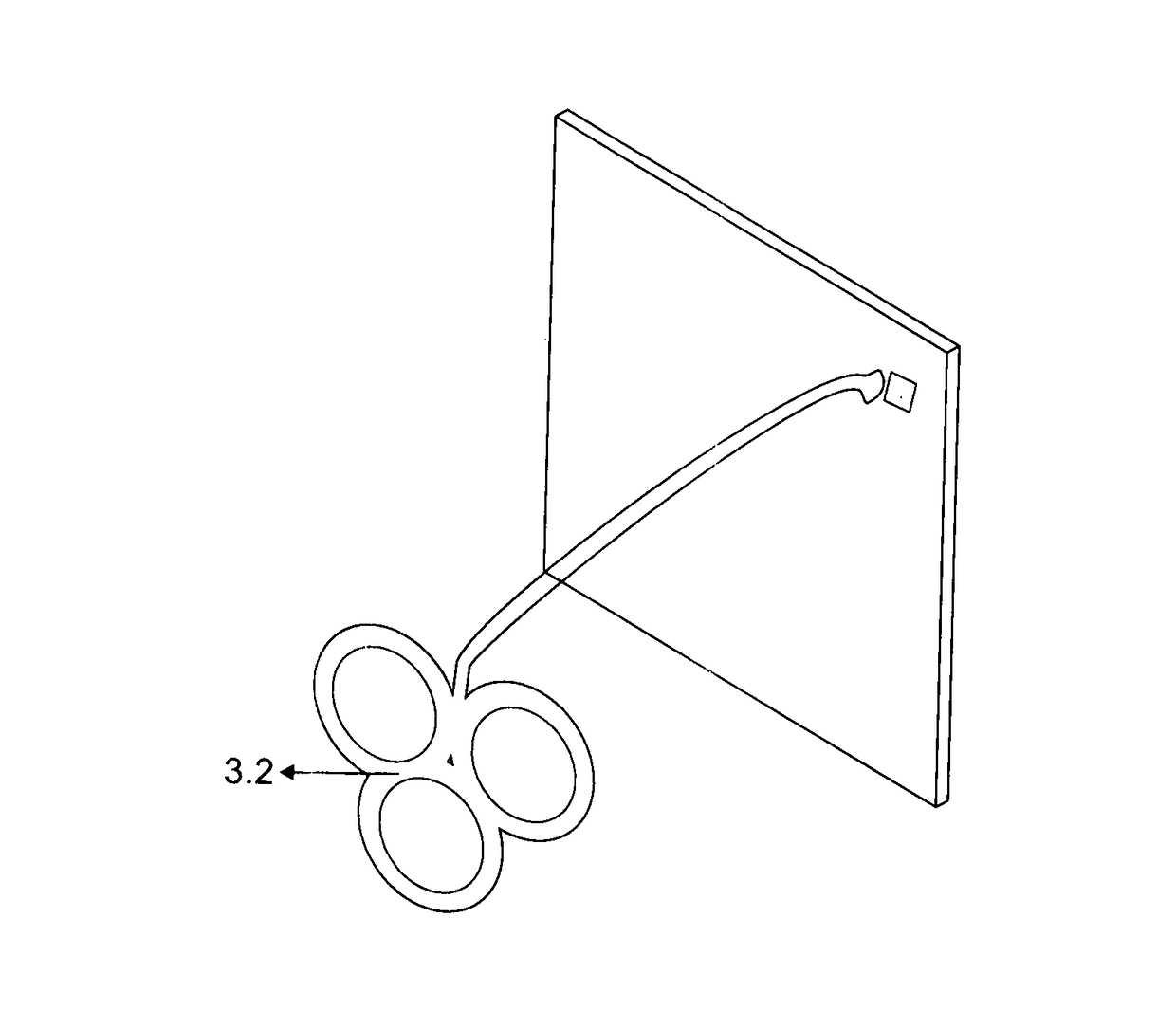
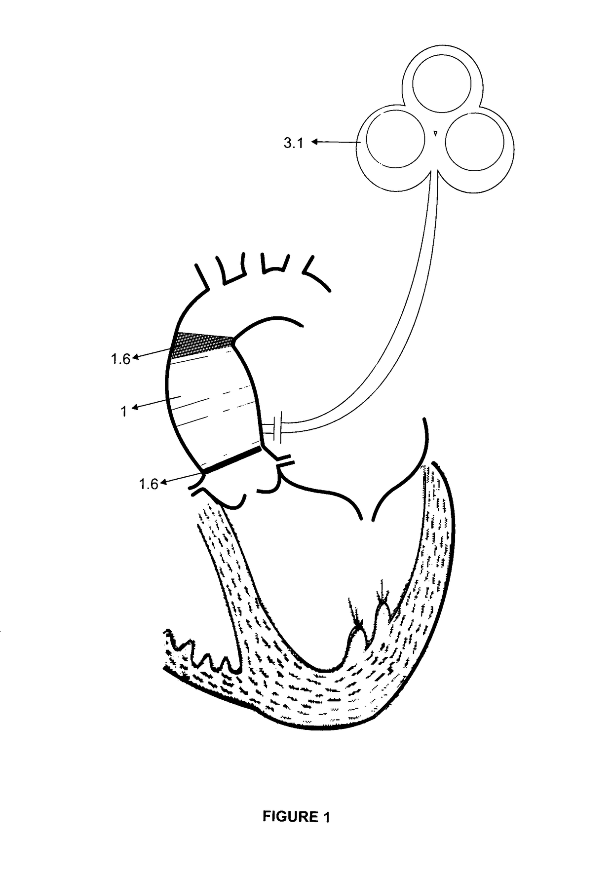
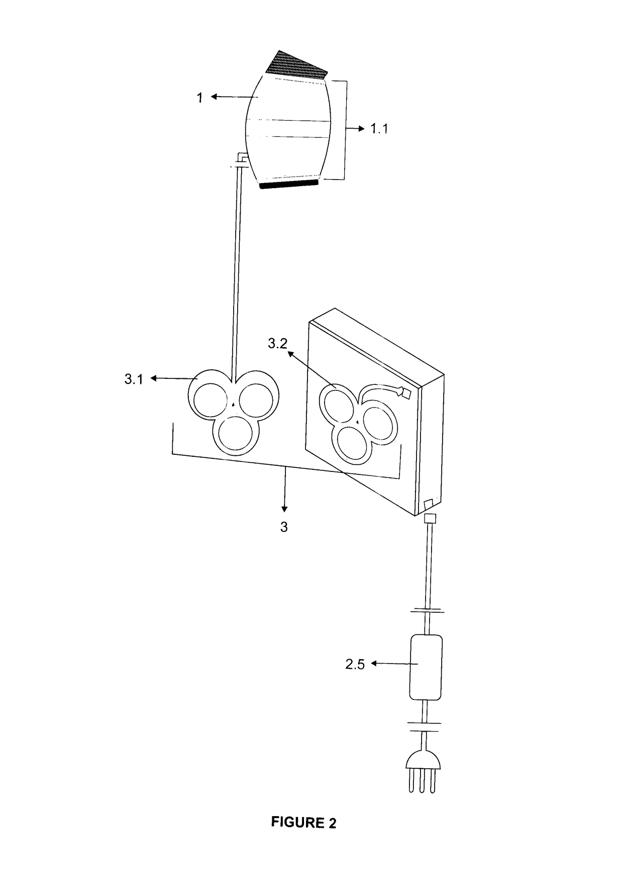
[0040]The invention is mainly composed of endovascular heart assist device (1), the control unit (2) and the wireless energy transfer apparatus (3). Endovascular heart assist device (1) is made up of the blood pump motor inside the device (1.1), the rotor (1.2), stator (1.3), the roller bearing (1.5) supported with magnetic bearing (1.4) and the wire cage (1.6) parts. The body of blood pump motor (1.1) consists of two parts; input (1.1.2) and the output part (1.1.3). Moreover, the input part (1.1.2) and the output part (1.1.3) contain propeller blades relieving turbulence (diffuser) (1.1.1). The rotor (1.2) comprises at least two helical propeller blades (1.2.1) without a pin (axis). Stator (1.3) includes electric coils (1.3.1) on it. The rotor (1.2) revolves freely with the propulsion received from this electrical coil (1.3.1) on the roller bearing (1.5) supported with magnetic bearing (1.4). Through rotation of the rotor (1.2), the helical propeller blades (1.2.1) propel the blood...


PUM


Abstract

The invention is a heart assist device which has been developed in order to maintain the blood circulation in end-stage heart patients who do not respond to medical treatment, and it has been designed in size and shape so that it can be installed into the anatomically spacious root sections of the aorta and main pulmonary artery. With its small volume, and exceptional motor design without a shaft, the device, which contains a brushless, asynchronous and three-phase electric motor, will consume much less energy. The three-phase current required for the motor is provided from the power supply outside the body through the synchronous and wireless transmission of three phases. The invention is about a permanent endovascular cardiac support device which contains a three-phase, brushless, asynchronous electric motor, and the required energy is provided through the three-phase wireless power transmission from outside the body.

Description

TECHNICAL FIELD[0001]The invention is about a new generation small heart assist device to be inserted into the ascending aorta and which has been developed in order to maintain blood circulation in the patients with severe heart failure. The device comprises a specially designed brushless electric motor and inside the rotor, which has no rotating shaft, propeller blades are located and they propel blood. Uninterruptible three-phase electrical power transmission, required to run this asynchronous three-phase motor, is provided from outside the body wirelessly. Since all electrical and electronic apparatus take place outside the patient's body, it is possible to update them easily. The invention is about a permanent new generation heart assist device placed into the major arteries and wider root partition of the major arteries.BACKGROUND[0002]Heart assist devices are vital devices in patients with end-stage heart diseases when heart muscle contractions are insufficient, and when no re...

Claims


Application Information

Patent Timeline
Patent Type & Authority Patents(United States)
IPC IPC(8): A61N1/362A61M1/12A61M1/10A61M60/139A61M60/216A61M60/422A61M60/515A61M60/569A61M60/82A61M60/825A61M60/873
CPCA61M1/1036A61M1/125A61M1/12A61M2210/127A61M1/101A61M1/1005A61M1/1013A61M1/1015A61M1/1031A61M1/1086A61M1/122A61M1/127A61M2205/0233A61M2205/16A61M2205/3334A61M2205/8243A61M60/82A61M60/419A61M60/422A61M60/148A61M60/216A61M60/569A61M60/515A61M60/825A61M60/873A61M60/139
Inventor BULENT, ORANOMER FARUK, ORANELIF ORAN, AVCI
Owner BULENT ORAN
Learn More