Hadron therapy installation comprising an imaging device

a technology of imaging device and hadron, which is applied in the field of hadron therapy installation comprising an imaging device, can solve the problem of limiting the access to the patient as little as possibl

Active Publication Date: 2018-11-13
ION BEAM APPL
View PDF7 Cites 2 Cited by
  • Summary
  • Abstract
  • Description
  • Claims
  • Application Information

AI Technical Summary

Benefits of technology

[0018]It will be noted that such an arrangement of the imaging device in the hadron therapy installation requires a very reduced bulk. In its position retracted at the irradiation unit, the imaging device hinders the access to the patient as little as possible. In its lateral deployed position relative to the target volume, the imaging device is ideally arranged to take images during the treatment of the patient and to have an optimal view of the target volume. The fact that the imaging device is secured in rotation with the irradiation device prevents any risk of collision with the latter. The translational movement relative to the irradiation unit between the retracted position and the deployed position is a movement that takes up little space and also reduces the risk of accidental collisions. This translational movement may furthermore be implemented with relatively simple and very reliable means. It will further be appreciated that the combination of a translation and a pivoting movement of the first arm makes it possible to obtain an optimal arrangement of the imaging device deployed relative to the target volume, while ensuring a compact retracted position thereof.
[0024]One simple and reliable embodiment of the device for pivoting the first arm comprises a guideway, which is immobile in a reference system secured to the irradiation unit, and a slide, which is supported by the first arm and arranged slidingly in the guideway. This guideway then comprises a first linear guide portion, to impart a translational movement to the first arm starting from its retracted position, such that the first arm remains substantially parallel to itself during said first translational movement, and a second curved guide portion, to give the first arm a pivoting movement about cylindrical articulation, that pivoting movement being superimposed on the translational movement so as to cause the first piece of imaging equipment to move laterally away from the target volume, when the first piece of equipment comes closer to the target volume.
[0026]In this advantageous embodiment, the first piece of equipment and / or the second piece of equipment of the imaging device are, in their respective retracted positions, completely or practically completely received inside the cover. Thus, any risk of collision of an object or person with the imaging device in the retracted position is avoided as effectively as possible.

Problems solved by technology

In its position retracted at the irradiation unit, the imaging device hinders the access to the patient as little as possible.

Method used


Image

  • Hadron therapy installation comprising an imaging device
  • Hadron therapy installation comprising an imaging device
  • Hadron therapy installation comprising an imaging device

Examples


first embodiment

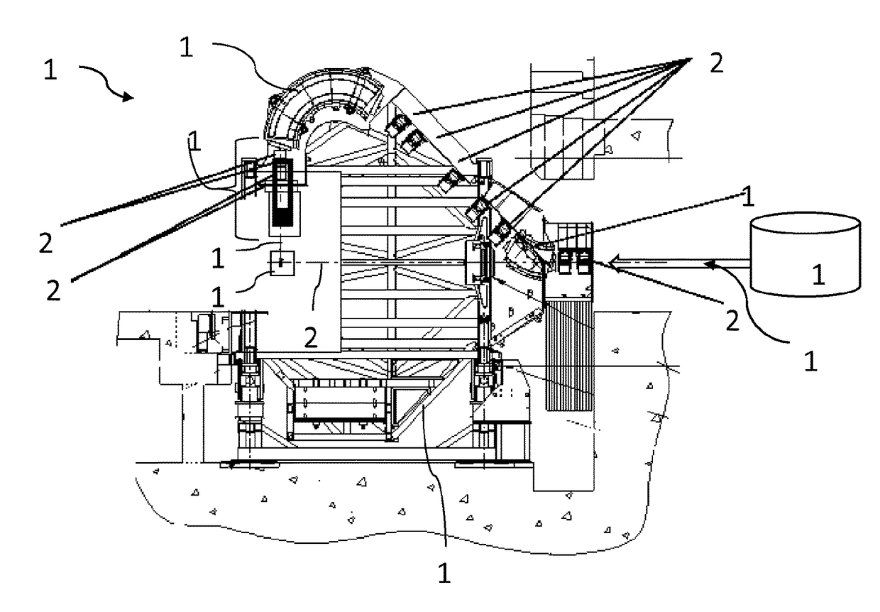
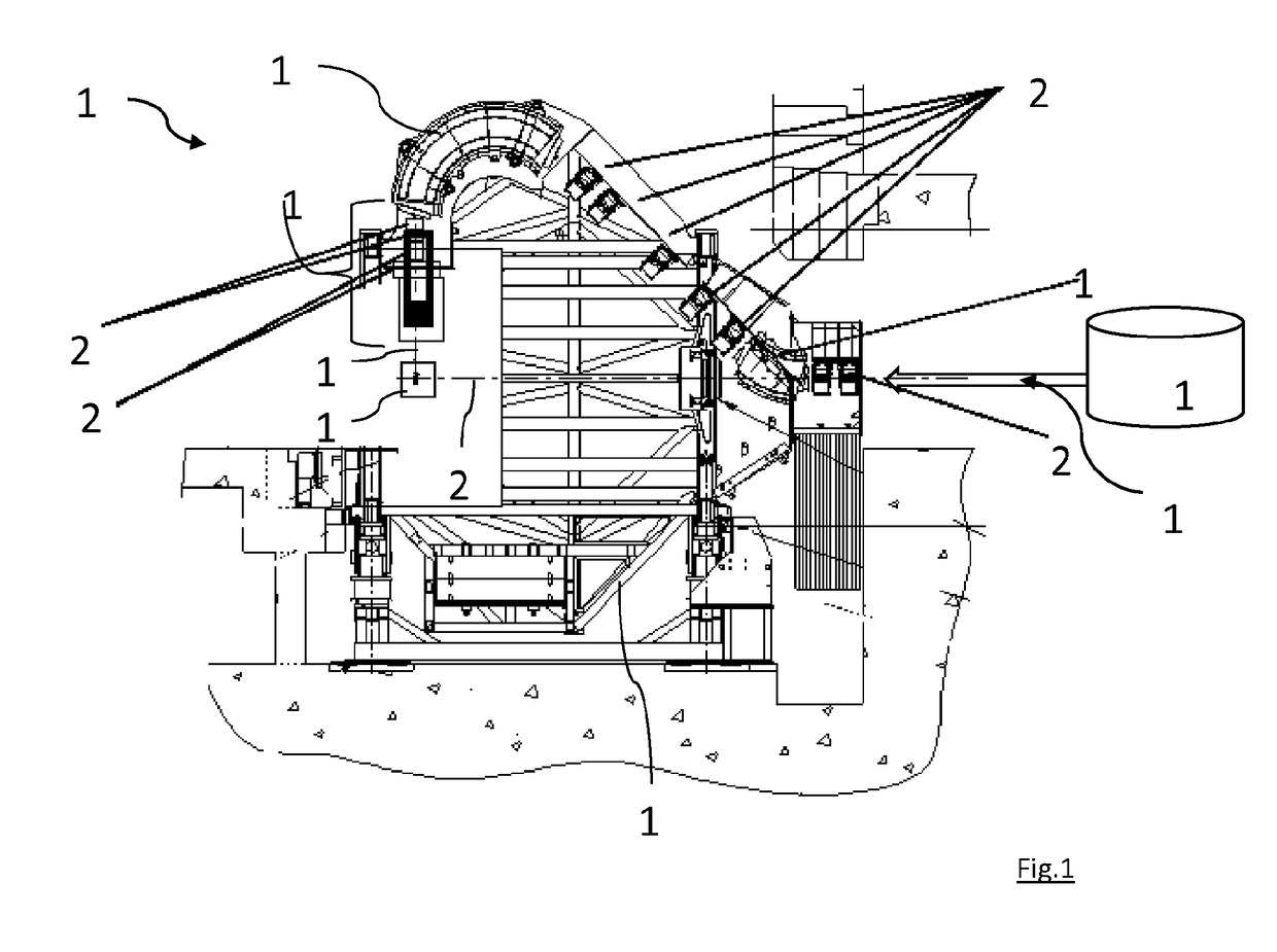
[0067]FIG. 1 shows the hadron therapy installation 100. This installation comprises: a generator 16 capable of generating a hadron beam 17, for example a cyclotron, a synchrotron or a synchrocyclotron; an isocentric rotary gantry 18 capable of rotating by an angle of 360° about the axis of rotation 22; and a beam transport line supported by the isocentric rotary gantry 18.

[0068]The beam transport line comprises an inlet 24 for the hadron beam 17, an irradiation unit 100 for delivering a treatment beam 17′ on a target volume 15 centered on the axis of rotation 22, as well as magnetic dipoles 19a, 19c for deflecting the beam and focusing means 20 for focusing the hadron beam, making it possible to transport the hadron beam 17 from the inlet 24 toward the irradiation unit 1. At the outlet of the irradiation unit 1, the treatment beam 17′ is oriented substantially perpendicular to the axis of rotation 22. The irradiation unit 1 comprises a nozzle 2 generally comprising monitoring means ...

second embodiment

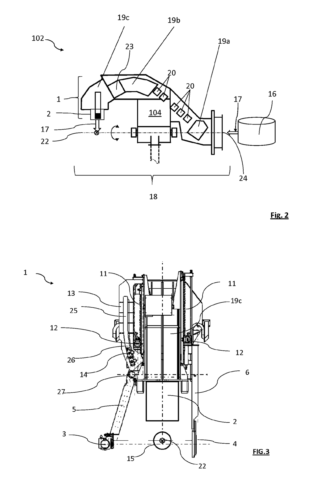
[0071]FIG. 3 shows the irradiation unit 1 of the second embodiment in more detail using a cross-section perpendicular to the axis of rotation 22. One can in particular see the last magnetic dipole 19c′ with the outlet nozzle 2.

[0072]Reference 3 indicates a piece of x-ray producing equipment, comprising an x-ray source. Reference 4 indicates a piece of x-ray receiving equipment. In FIG. 3, each of the two pieces of equipment 3 and 4 is shown in its deployed position, in which it is arranged in the immediate vicinity of the target volume 15. Situated on either side of the plane containing the axis of the treatment beam 17′ and the axis of rotation 22, the two pieces of equipment 3 and 4 cooperate in this deployed position so as to form an XR imaging device.

[0073]The x-ray producing equipment 3 and the x-ray receiving equipment 4 are both secured in rotation with the irradiation unit 1 and translatable relative to the irradiation unit 1, between a retracted position, in which they are ...


PUM


Abstract

The invention relates to a hadron therapy installation that comprises an irradiation unit (1) supported by a rotary support structure, so as to be able to rotate around a target volume (15) centered on the axis of rotation (22), to deliver a treatment beam (17) from different angles on the target volume (15). An imaging device (3, 4) is secured in rotation with the irradiation unit (1) and translatable relative to the irradiation unit (1) between a retracted position at the irradiation unit (1) and a lateral deployed position relative to the target volume (15), such that in its deployed position, the imaging device (3, 4) can rotate around the target volume (15) together with the irradiation unit (1). Such an installation can be used for a cone beam computed tomography method and / or a fluoroscopic imaging method on a patient to be treated in the hadron therapy installation.

Description

TECHNICAL FIELD[0001]The present invention relates to a hadron therapy installation comprising an imaging device. It also relates to an imaging method using cone beam computed tomography, as well as a fluoroscopy method in such a hadron therapy installation.BACKGROUND OF THE INVENTION[0002]The recent hadron therapy techniques for treating cancer make it possible to deliver a dose precisely on a target volume, for example a tumor, while preserving the surrounding tissue. Such a hadron therapy installation comprises a particle accelerator producing a charged particle beam, means for transporting the beam, and an irradiating unit. The irradiating unit delivers a dose distribution on the target volume and generally comprises means for monitoring the delivered dose, for example such as an ionizing chamber, as well as monitoring means for the beam, for example such as a collimator or scanning magnets based on the delivery mode of the beam used.[0003]Most hadron therapy installations compr...

Claims


Application Information

Patent Timeline
Patent Type & Authority Patents(United States)
IPC IPC(8): A61N5/10A61B6/03A61B6/00A61B6/10
CPCA61N5/1048A61B6/032A61B6/035A61B6/4085A61B6/487A61N5/1081A61N5/1049A61N2005/1087A61B6/105A61B6/4429A61B6/547A61N2005/1061
Inventor DEBATTY, ALEXANDREAMELIA, JEAN-CLAUDEDE NEUTER, SEBASTIEN
Owner ION BEAM APPL
Why Eureka
Try Eureka