
Contact for a high-voltage vacuum arc extinguishing chamber

a contact and vacuum arc technology, applied in the direction of air-break switches, high-tension/heavy-dress switches, electrical equipment, etc., can solve the problems of increasing the contact resistance between the contacts, wear and aging of the contacts, and the electric arc is extremely difficult to extinguish in vacuum, so as to reduce the heat of the vacuum chamber

Active Publication Date: 2018-11-13
ZHEJIANG ZIGUANG ELECTRIC APPLIANCE
View PDF15 Cites 2 Cited by
  • Summary
  • Abstract
  • Description
  • Claims
  • Application Information

AI Technical Summary

Benefits of technology

This patent describes a contact for a high-voltage vacuum arc extinguishing chamber that can be used as both a moving contact and a fixed contact. The contact is designed to rapidly extinguish electric arcs by generating an axial magnetic field and a circumferential magnetic field that intersect with each other. This reduces the heat generated by the contacts and prevents burning of the contacts. Additionally, the contacts are directly connected with the conductive connecting piece, which provides a firm overall structure and a long use life.

Problems solved by technology

However, if the voltage is in the level of 50 kv or 110 kv, the electric arc is extremely difficult to extinguish in vacuum.
With increase of the number of switching, the electric arc generated in the high-voltage state will continuously burn the contacts, leading to the wear and aging of the contacts, which further increases the contact resistance between the contacts.
However, these materials have a poor heat dissipation property and high heat will be generated in the vacuum chamber by the heat of electric arc and increase of the contact resistance between the contacts.
To this end, the use performance and use life of the vacuum arc extinguishing chamber and components thereof will be seriously affected, and the application level and switching capacity of the high-voltage vacuum arc extinguishing chamber will be affected as well.
Even though such a configuration could reduce the contact resistance, the circuit break in high-voltage environment could not be addressed, and the electric arc could not rapidly extinguish in high-voltage environment to reduce burning of the contacts by the electric arc.

Method used


Image

  • Contact for a high-voltage vacuum arc extinguishing chamber
  • Contact for a high-voltage vacuum arc extinguishing chamber
  • Contact for a high-voltage vacuum arc extinguishing chamber

Examples


first embodiment

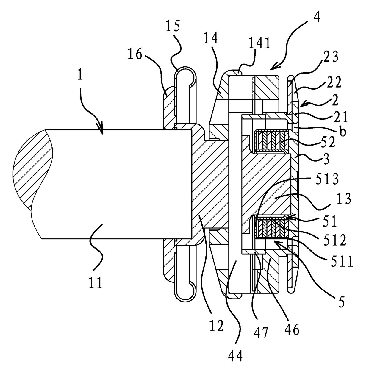
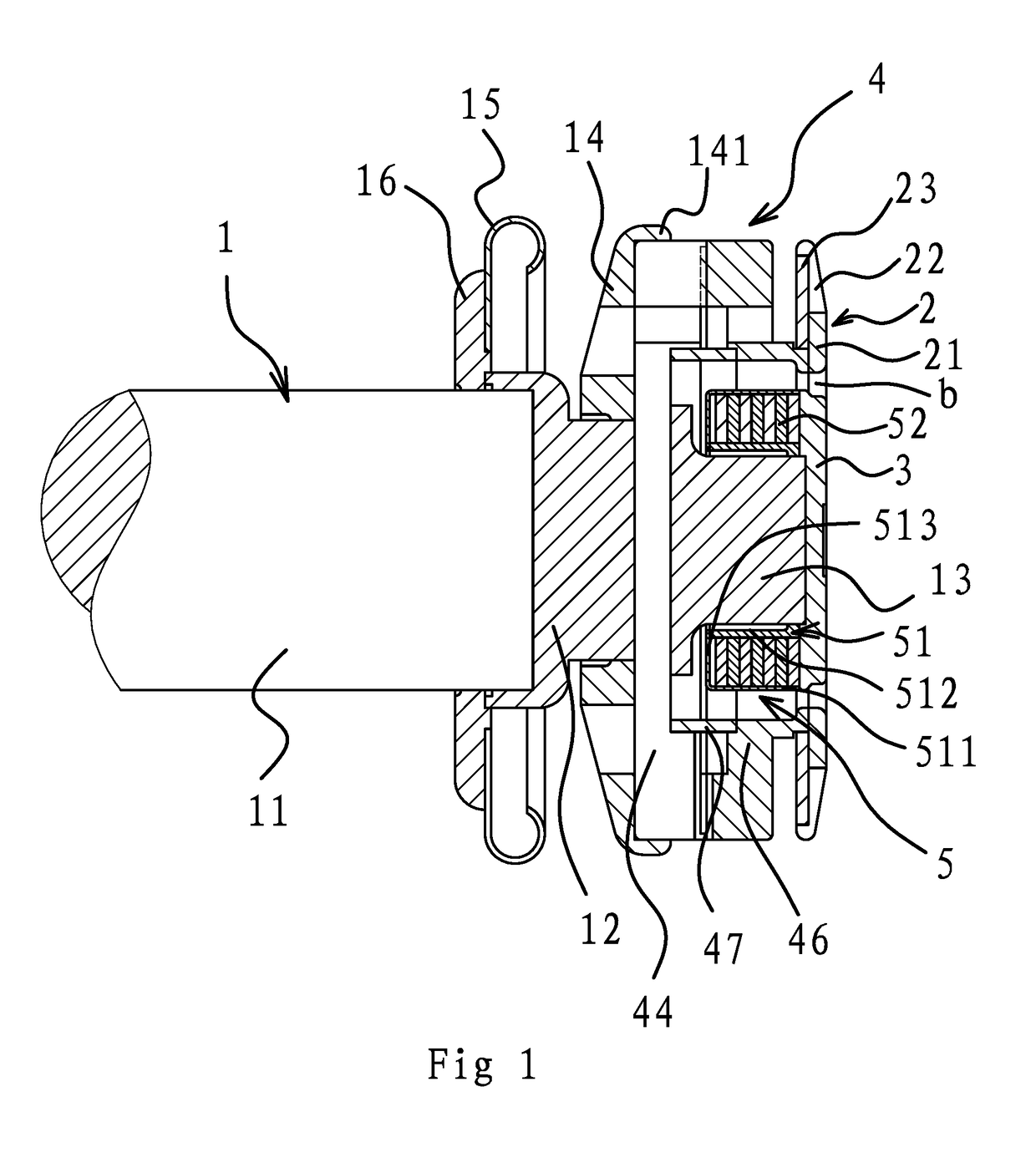
[0035]As shown in FIG. 1, the contact for the high-voltage vacuum arc extinguishing chamber of the invention could be used as a moving contact or a fixed contact, including a conductive connecting piece 1, an annular outer contact 2 and an inner contact 3 which is located within the ring of the outer contact 2 and does not contact with the outer contact 2. The electric arc could rapidly extinguish in high-voltage environment and the heat in the vacuum chamber is reduced by using the contact of the invention.

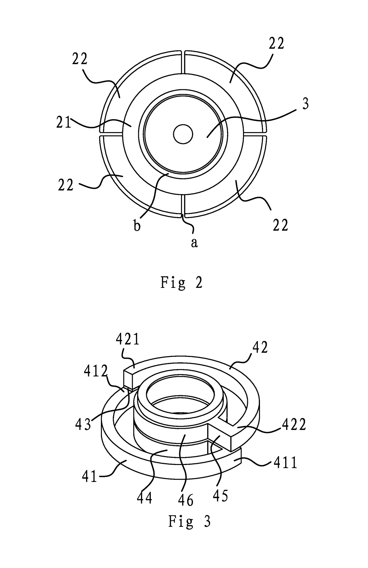
[0036]In particular, referring to FIGS. 1 and 2, the outer contact 2 is annual and the intermediate portion 21 is made of copper-chromium alloy materials. Four sector pieces 22 are provided on the edge of the intermediate portion 21 and a spacing (a) exits between the adjacent sector pieces 22. Each sector piece 22 is tilted relative to the intermediate portion 21. As such, when the contacts are in contact with each other, only the intermediate portions 21 will be in contact and ...

second embodiment

[0044]The second embodiment is substantially identical to the first embodiment except that the openings of adjacent horseshoe cores 52 are stacked in the same angle and in the same direction, as shown in FIG. 5. Such an arrangement could speed up extinction of the electric arc. The other aspects are omitted herein for brevity.

third embodiment

[0045]The third embodiment is substantially identical to the first embodiment except that the openings of a half of the horseshoe cores 52 are aligned on the upper layer and those of the other half are aligned on the lower layer, in which the openings of the upper layer of the horseshoe cores 52 are arranged normal to those of the lower layer of the cores. Four poles, i.e., the ends of the cores, will be formed in the said configuration, which could form an intersectional magnetic field and has a better arc extinguishing effect. The other aspects are omitted herein for brevity.


PUM


Abstract

The invention provides a contact for a high-voltage vacuum arc extinguishing chamber. The contact of the invention includes a conductive connecting piece, an annular outer contact and an inner contact which is located within the ring of the outer contact and does not contact with the outer contact. The conductive connecting piece, inner contact and outer contact are coaxial and the contact surface of the inner contact is on the same plane as that of the outer contact. The outer contact is fixed on the conductive connecting piece. An axial magnetic field means is covered outside of the conductive connecting piece for generating an axial magnetic field. The axial magnetic field means is fixedly connected with the conductive connecting piece. The inner contact is fixed on the conductive connecting piece. A circumferential magnetic field means is covered outside of the conductive connecting piece for generating a circumferential magnetic field.

Description

RELATED APPLICATIONS[0001]This application is a national stage entry of International Application No. PCT / CN2014 / 073583, filed Mar. 18, 2014, and claims benefit of Chinese Patent Application No. CN201410025353.7, filed Jan. 20, 2014.[0002]The above applications and all patents, patent applications, articles, books, specifications, other publications, documents, and things referenced herein are hereby incorporated herein in their entirety for all purposes. To the extent of any inconsistency or conflict in the definition or use of a term between any of the incorporated publications, documents, or things and the text of the present document, the definition or use of the term in the present document shall prevail.BACKGROUND OF THE INVENTIONField of Invention[0003]The present invention relates to the technical field of the vacuum arc extinguishing chamber, and particularly to a contact for a high-voltage vacuum arc extinguishing chamber.Related Art[0004]In electric power systems, the swi...

Claims


Application Information

Patent Timeline
Patent Type & Authority Patents(United States)
IPC IPC(8): H01H33/664
CPCH01H33/664H01H33/6645H01H33/6644
Inventor ZHOU, HEMINGLIU, ZHIYUANLIN, HAIYONG
Owner ZHEJIANG ZIGUANG ELECTRIC APPLIANCE
Learn More