
Wearable sensor system with an article of clothing and an electronics module, article of clothing for a wearable sensor system, and electronics module for a wearable sensor system

a technology of wearable sensor and electronics module, which is applied in the direction of sensing record carriers, coupling device connections, garments, etc., can solve the problems of wear on the wearable sensor system, the inability to firm connection to the expensive electronics module, and the inability to compensate the manufacturing tolerance of the deflector of the holder. , to achieve the effect of further reducing the wear on the contact elements and reducing the manufacturing tolerances

Active Publication Date: 2018-11-20
WORKAROUND GMBH
View PDF8 Cites 7 Cited by
  • Summary
  • Abstract
  • Description
  • Claims
  • Application Information

AI Technical Summary

Benefits of technology

The invention aims to prevent wear and tear on the contact elements of an electronics module and the retainer by avoiding shear forces during insertion. The contact element is fixedly connected to the housing and movably connected to the circuit board, which compensates for manufacturing tolerances and prevents wear on the electrical connection. This results in a more robust and durable connection between the circuit board and the contact element.

Problems solved by technology

At the same time, the electronics module is the most costly component of the sensor system.
Therefore, a firm connection to the expensive electronics module is out of the question since the comparatively expensive electronics module would also need to be frequently replaced then.
The wearable sensor system, however, is also exposed to wear here since owing to the frequent exchange of the electronics module, the contact elements of the electronics module that connect the circuit board of the electronics module to the operational element of the article of clothing, and the mating contacts of the retainer will wear down.

Method used


Image

  • Wearable sensor system with an article of clothing and an electronics module, article of clothing for a wearable sensor system, and electronics module for a wearable sensor system
  • Wearable sensor system with an article of clothing and an electronics module, article of clothing for a wearable sensor system, and electronics module for a wearable sensor system
  • Wearable sensor system with an article of clothing and an electronics module, article of clothing for a wearable sensor system, and electronics module for a wearable sensor system

Examples


Embodiment Construction

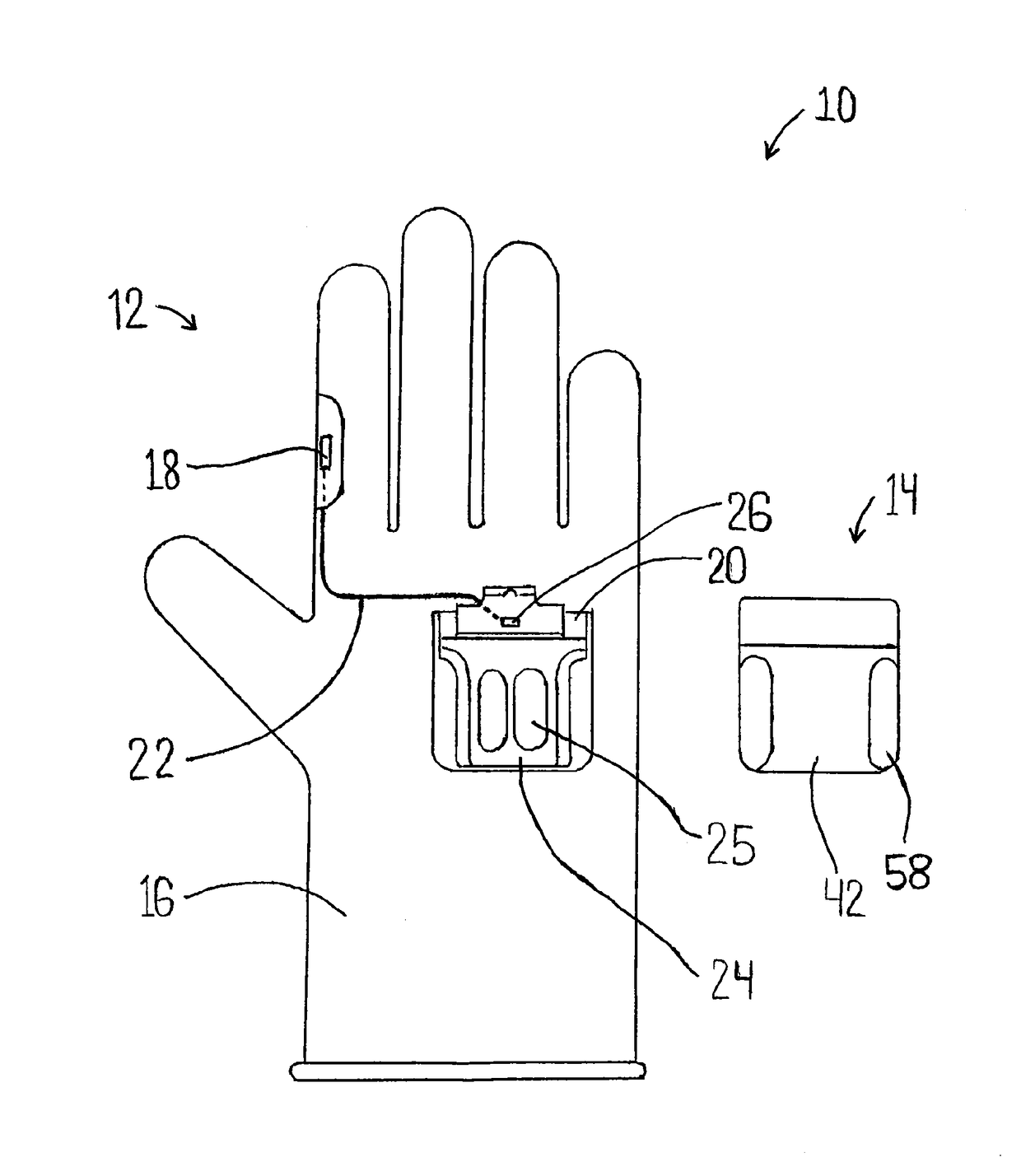
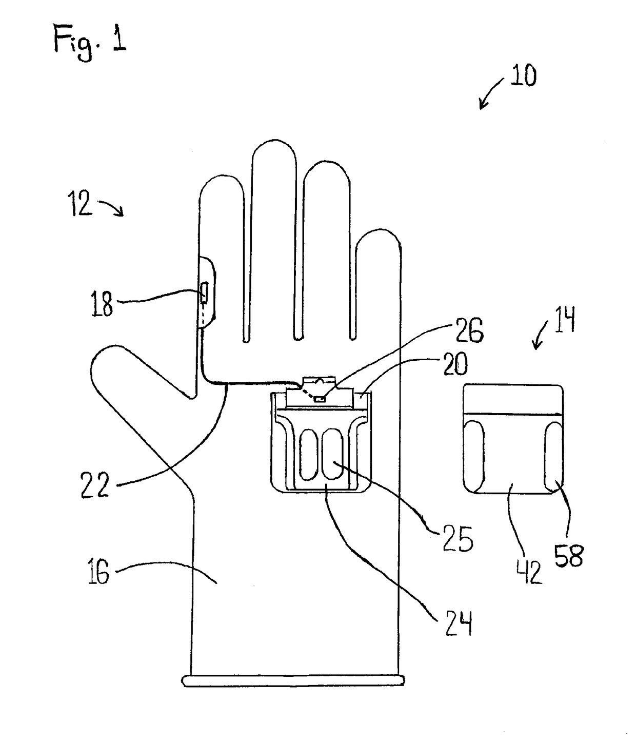
[0039]FIG. 1 illustrates the wearable sensor system 10 with an article of clothing 12 and an electronics module 14.

[0040]The article of clothing 12 includes a glove 16, an electric operational element 18, for example a pushbutton, a holder 20, and a cable 22.

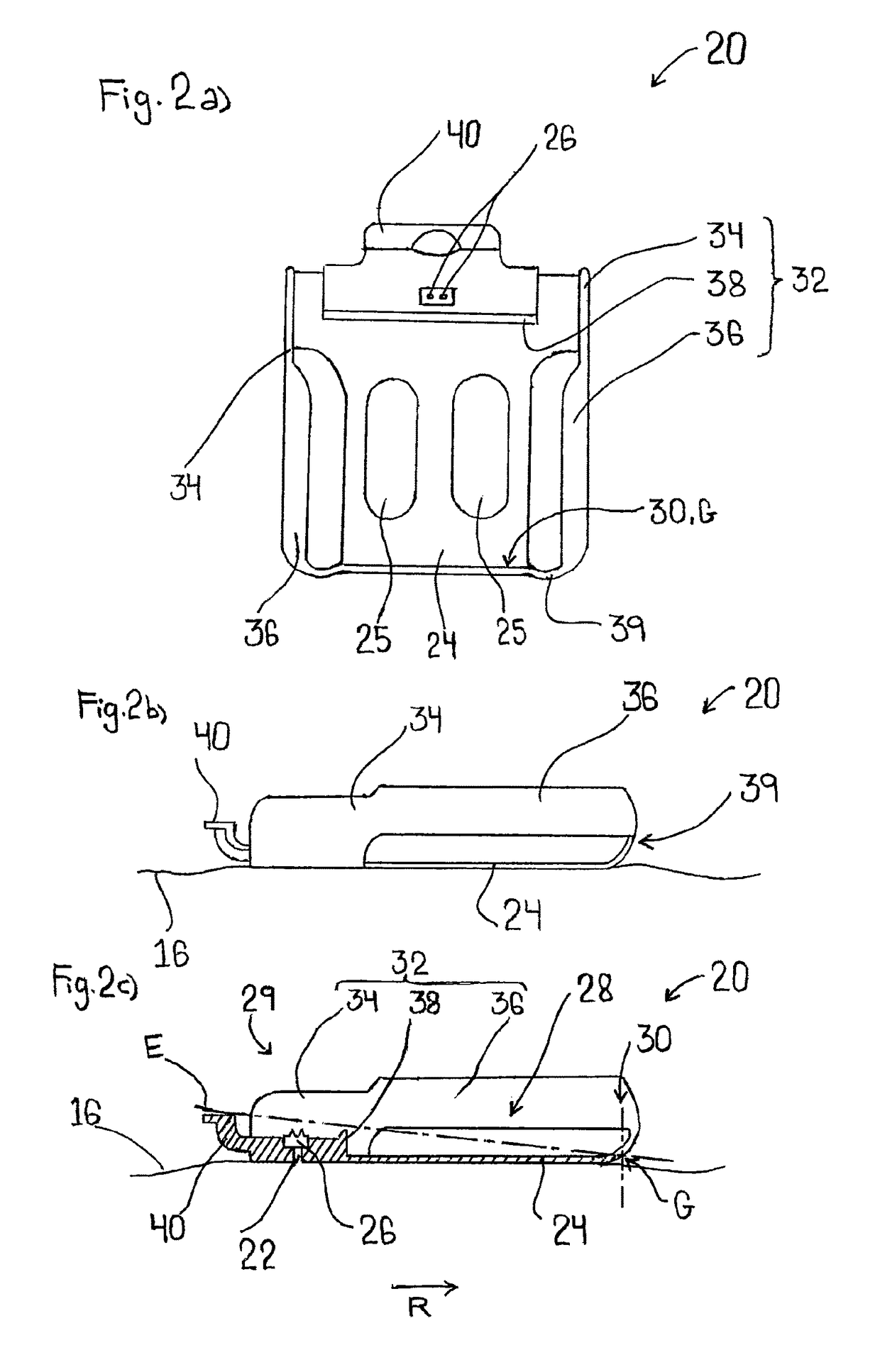
[0041]The holder 20 is illustrated in detail in FIGS. 2a to 2c and has a bottom 24 and two mating contacts 26 which are arranged on the bottom 24. The mating contacts 26 may be spring mounted in relation to the bottom 24 and are, for example, in the form of spring contacts.

[0042]The bottom 24 is attached to the glove 16, for example by means of a hot-melt adhesive, so that the entire holder 20 is attached to the glove 16. By way of example, the bottom 24 has openings 25 that serve for an air supply to the hand of the user within the glove 16.

[0043]As illustrated in FIG. 1, the cable 22, which may likewise be attached to the glove 16 by means of a hot-melt adhesive, connects the electric operational element 18 to the mating conta...


PUM


Abstract

A wearable sensor system has an article of clothing and an electronics module. The electronics module includes a housing, a circuit board, and a contact element. The article of clothing includes a glove, an operational element, and a holder for attaching the electronics module having a receiving space and a mating contact. The guide being configured such that the contact element performs one of a linear movement and a pivoting movement toward the bottom when moving to the final position with respect to the mating contact. Further, an article of clothing and an electronics module for the wearable sensor system are shown.

Description

FIELD OF THE INVENTION[0001]The present invention relates to a wearable sensor system including an article of clothing and an electronics module, an article of clothing for a wearable sensor system, and an electronics module for a wearable sensor system.BACKGROUND OF THE INVENTION[0002]Wearable sensor systems typically include an electronics module in which a circuit board having a controller for the sensor system is provided and which may also contain a sensor such as an optical barcode scanner. This electronics module has to be attached to an article of clothing so that it is carried by the user all the time. At the same time, the electronics module is the most costly component of the sensor system.[0003]The article of clothing itself may comprise a glove, and it is further known to provide an operational element on the glove. The operational element may be a switch, for example, which serves as an input device of the electronics module. To this end, the operational element needs ...

Claims


Application Information

Patent Timeline
Patent Type & Authority Patents(United States)
IPC IPC(8): H01R4/58A41D19/00H01R33/94H01R12/71H01R13/24H01R13/631H01R33/97
CPCH01R33/94A41D19/0024A41D19/0037H01R33/97H01R13/24H01R13/631H01R12/714A41D19/0027G06F3/014G06K7/10396G06K7/10881G06K2007/10534
Inventor BRUNNBAUER, KONSTANTINSITTIG, HANS CHRISTIANGUENTHER, PAULGUTMANN, TOBIASGIRARDET, JONAS
Owner WORKAROUND GMBH
Learn More