
Radio communication system and distance measuring method

a radio communication system and distance measurement technology, applied in direction finders using radio waves, anti-theft devices, instruments, etc., can solve the problems of difficult distance measurement, incorrect relative distance between them,

Active Publication Date: 2018-11-27
TOYOTA JIDOSHA KK
View PDF24 Cites 3 Cited by
  • Summary
  • Abstract
  • Description
  • Claims
  • Application Information

AI Technical Summary

Benefits of technology

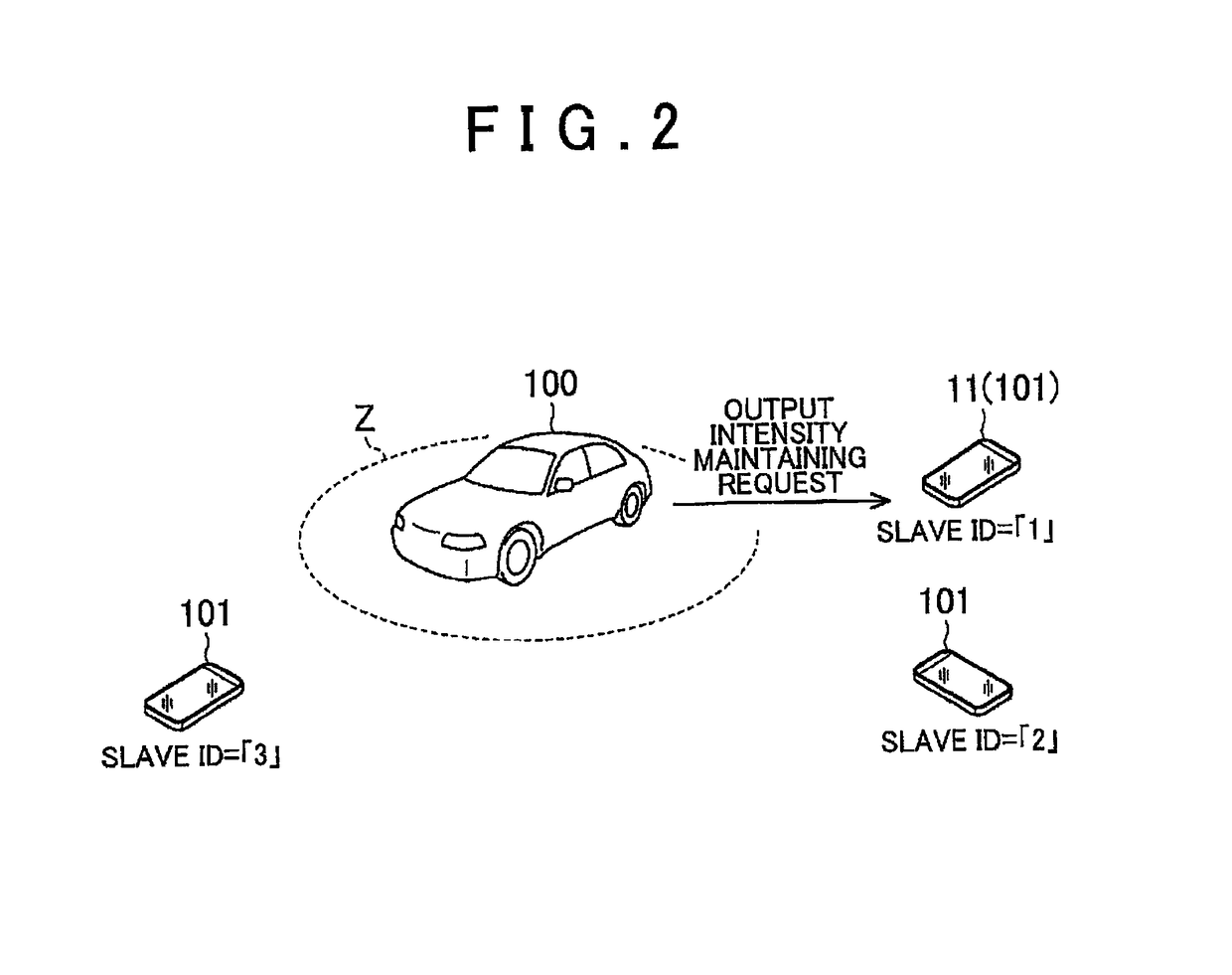
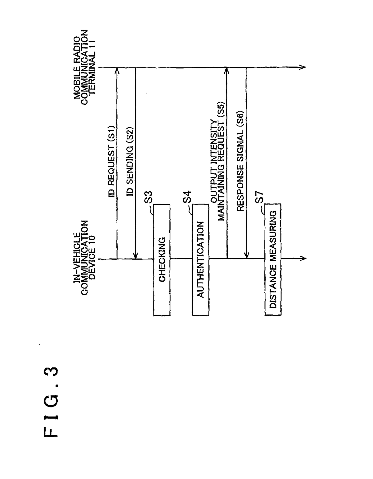
[0010]According to the aspects described above, the radio wave intensity of the measuring signal is controlled at a pre-set intensity and, then, distance measuring is performed based on the radio wave intensity of the measuring signal or on a signal to which the radio wave intensity of the measuring signal is added as information. This configuration therefore allows distance measuring to be performed even for a radio communication terminal that has the general-purpose communication function that makes variable the sending radio wave intensity.
[0013]According to the aspects described above, after the above-described output control signal is received, the sending radio wave intensity of the radio communication terminal becomes constant. This configuration therefore allows distance measuring to be performed even for a radio communication terminal that has the general-purpose communication function that makes variable the sending radio wave intensity.
[0014]In the first aspect described above, the output control unit may send the output intensity maintaining request to an authenticated radio communication terminal. According to this aspect, the above-described output control signal is sent only to an authenticated radio communication terminal. This configuration therefore prevents unnecessary output control from being performed for a radio communication terminal that is present around the vehicle but is not authenticated.
[0016]According to this aspect, the above-described output control signal is sent to all the radio communication terminals each of which has the above-described identification information. This configuration therefore prevents the request, which sets the sending radio wave intensity to a predetermined level, from being sent at least to a mobile radio communication terminal that has not the identification information.
[0019]According to these aspects, the reception intensity of a radio wave sent from the in-vehicle communication device to the radio communication terminal with a predetermined intensity is detected by the radio communication terminal and its intensity information is returned to the in-vehicle communication device. Therefore, distance measuring may be performed on the vehicle side without having to control the sending radio wave intensity of the radio communication terminal. This configuration therefore allows distance measuring to be performed even for a radio communication terminal that has the general-purpose communication function that makes variable the sending radio wave intensity.

Problems solved by technology

However, in a radio communication system composed of an in-vehicle communication device and a mobile radio communication terminal, the following problem may arise.
That is, when the in-vehicle communication device measures the distance by communicating with the mobile radio communication terminal that has the function to make variable the sending radio wave intensity as with the device described in the above document, the relative distance between them may be incorrectly detected.
In other words, it is difficult to measure the distance when a general-purpose radio communication terminal is used as a terminal that wirelessly communicates with an in-vehicle communication device.

Method used


Image

  • Radio communication system and distance measuring method
  • Radio communication system and distance measuring method
  • Radio communication system and distance measuring method

Examples


first embodiment

(First Embodiment)

[0029]A first embodiment is described below in which a radio communication system for vehicles and the distance measuring method used in the radio communication system are embodied.

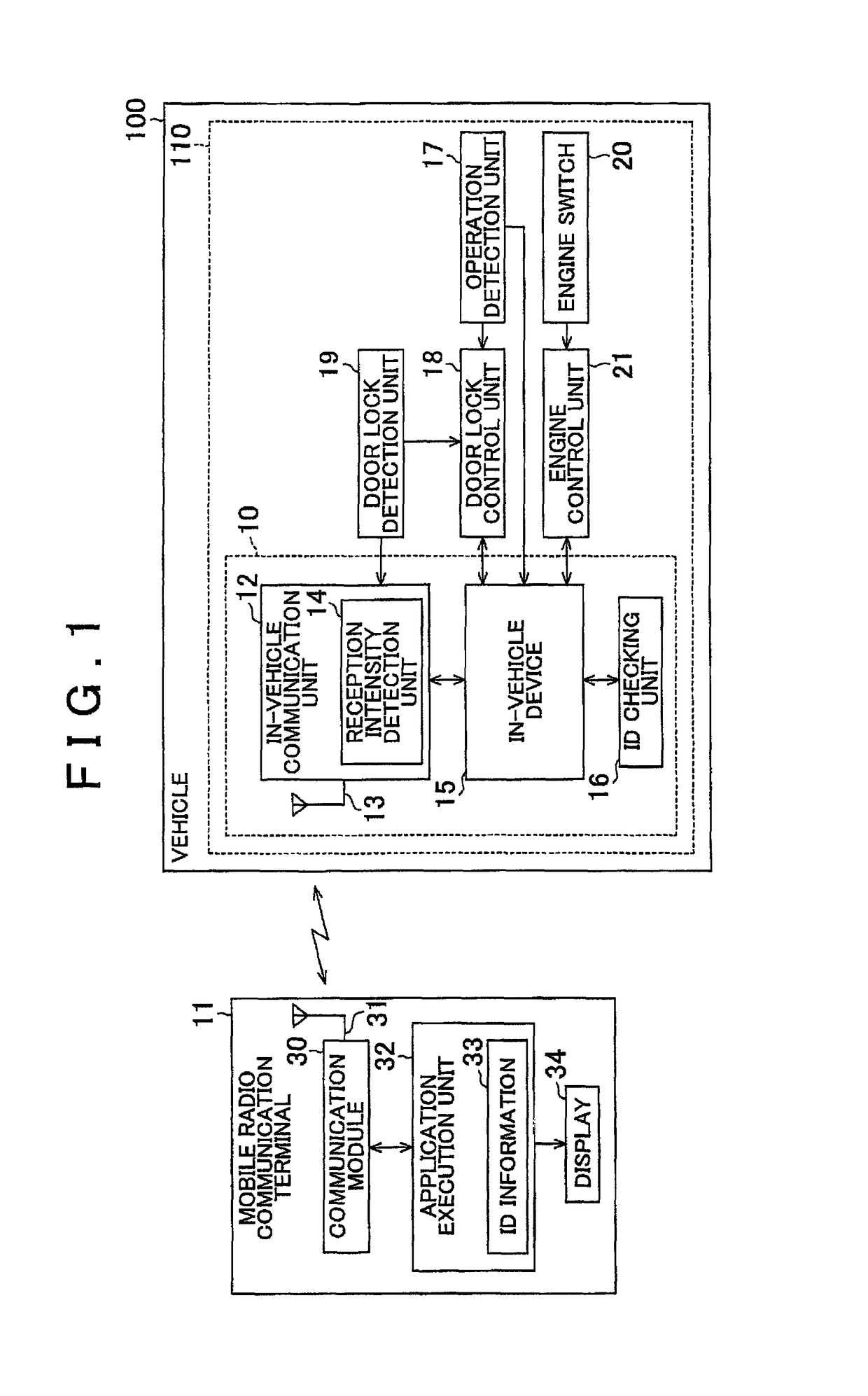
[0030]As shown in FIG. 1, a vehicle 100 in which the radio communication system and the radio communication method, both specifically designed for vehicles, are used is equipped with an electronic key system 110. This electronic key system 110 is used for radio communication with a mobile radio communication terminal 11. The mobile radio communication terminal 11 in this embodiment is a multi-function phone (smartphone) connectable to a general-purpose communication network with its function varying according to the machine type.

[0031]The electronic key system 110 includes an in-vehicle communication device 10 that wirelessly communicates with the mobile radio communication terminal 11. The in-vehicle communication device 10 includes an in-vehicle communication unit 12 that performs radi...

second embodiment

(Second Embodiment)

[0050]Next, a second embodiment of a radio communication system and its distance measuring method is described with emphasis on the difference from the first embodiment. Note that the basic configuration of the radio communication system and its distance measuring method in this embodiment is similar to that of the first embodiment. In the drawings, the same reference numeral is given to substantially the same component as that in the first embodiment, and the duplicated description will be omitted.

[0051]As shown in FIG. 4, the in-vehicle communication unit 12 of the vehicle 100 may have a reception intensity detection unit for controlling the radio wave sending range but may have a reception intensity detection unit omitted that is provided only for measuring the distance. In addition, the in-vehicle communication unit 12 has the function to control the output to the in-vehicle communication antenna 13.

[0052]The communication module 30 of the mobile radio communi...

third embodiment

(Third Embodiment)

[0060]Next, a third embodiment of a radio communication system and its distance measuring method is described with emphasis on the difference, from the first embodiment. Note that the basic configuration of the radio communication system and its distance measuring method in this embodiment is similar to that of the first embodiment. In the drawings, the same reference numeral is given to substantially the same component as that in the first embodiment, and the duplicated description will be omitted.

[0061]As shown in FIG. 7, the mobile radio communication terminal 11 communicates also with an output management device 50, an output control unit capable of communication via Bluetooth (registered trademark), in this embodiment. In the mobile radio communication terminal 11, identification information 51 is registered to indicate that the application for the electronic key system is installed. In other words, all mobile radio communication terminals 11, in which the app...


PUM


Abstract

A radio communication system, in which radio communication is carried out between an in-vehicle communication device, mounted in a vehicle, and a radio communication terminal to detect a relative distance therebetween, includes an output control unit that controls a radio wave intensity of a measuring signal, which is sent from one of the in-vehicle communication device and the radio communication terminal, at a pre-set predetermined value; and a measuring unit that performs distance measuring on a vehicle side based on the radio wave intensity of the measuring signal controlled at the predetermined value or on a signal to which a value of the radio wave intensity of the measuring signal is added as information.

Description

BACKGROUND OF THE INVENTION[0001]1. Field of the Invention[0002]The present invention relates to a radio communication system and a distance measuring method.[0003]2. Description of the Related Art[0004]As a system for carrying out radio communication between an in-vehicle communication device and a user-owned radio communication terminal, a system is already known that can locks / unlocks the door of a vehicle without using a mechanical key. According to this system, when a user carrying an electronic key approaches the vehicle, the in-vehicle communication device checks the ID code of the electronic key. When the validity of the electronic key is successfully authenticated as a result of the checking and the electronic key enters a predetermined distance range from the vehicle position, the vehicle can be unlocked without having to insert the mechanical key into the cylinder lock of the vehicle. As an electronic key, though only a terminal conforming to the specification of the in-v...

Claims


Application Information

Patent Timeline
Patent Type & Authority Patents(United States)
IPC IPC(8): G01S3/02B60R25/24G01S11/06G01S5/14G08B21/02
CPCG01S11/06B60R25/245G08B21/0247G01S5/14
Inventor MURAKAMI, HIROKO
Owner TOYOTA JIDOSHA KK
Learn More