An ultra-small ulf/vlf rotating current antenna and signal amplitude-frequency modulation method

An ultra-small, high-current technology, applied to antennas, loop antennas, circuits, etc., can solve problems such as non-radiation, unfavorable maintenance, and easy destruction, and achieve the effect of small electric size

Active Publication Date: 2020-07-31
SOUTHEAST UNIV
View PDF2 Cites 0 Cited by
  • Summary
  • Abstract
  • Description
  • Claims
  • Application Information

AI Technical Summary

Problems solved by technology

[0004] The radiation efficiency of traditional antennas is limited by the size of the antenna aperture. If the electrical size of the antenna is too small, the efficiency of the antenna will be extremely low, and it will hardly even radiate
At present, there is no shortage of receivers with high sensitivity in the ULF / VLF frequency band. However, the wavelength of electromagnetic waves in the free space of the ULF and VLF frequency bands may reach hundreds to thousands of kilometers. The volume of the ULF / VLF transmitting system designed by conventional antenna methods very bulky, often requiring such figure 1 That is erected on many tall towers. For example, the world's most powerful VLF transmitter built by the U.S. Navy in Cutler, Maine covers an area of ​​2,000 acres and is erected on 26 iron towers with a height of 850-1,000 feet. The transmitter is easy to be destroyed in many combat environments, and it is not conducive to maintenance, especially when it needs to be moved, it must be carried by a giant air balloon or satellite, which is extremely impractical

Method used


Image

  • An ultra-small ulf/vlf rotating current antenna and signal amplitude-frequency modulation method
  • An ultra-small ulf/vlf rotating current antenna and signal amplitude-frequency modulation method
  • An ultra-small ulf/vlf rotating current antenna and signal amplitude-frequency modulation method

Examples


Embodiment Construction

[0027] The technical solution of the present invention will be further introduced below in combination with specific implementation methods and accompanying drawings.

[0028] This specific implementation mode discloses an ultra-small ULF / VLF rotating current antenna, and the design principle is firstly introduced below.

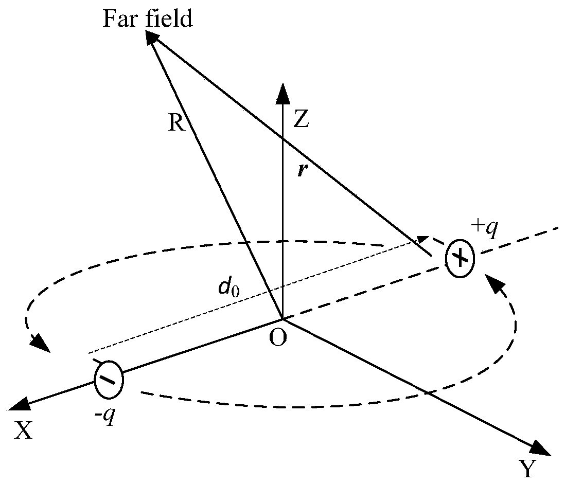
[0029] It is well known that a changing electric field induces a magnetic field, and a changing magnetic field induces an electric field. Electric and magnetic fields in turn induce each other to form electromagnetic waves that can propagate. Charges generate an electric field in space. If the charge is driven to make a certain movement, a changing electric field is generated in space, and then a magnetic field that interacts with the electric field is generated, and radiated electromagnetic waves may be generated. The electric field and magnetic field generated by the charge moving at a low speed (v<


PUM


Abstract

The invention discloses an ultra-small ULF / VLF rotating current antenna, comprising a light-emitting device and a turntable, wherein the turntable comprises a positive metal layer, a P-type semiconductor layer, an N-type semiconductor layer and a negative metal layer, which are arranged in sequence; the positive metal layer is provided with a light hole, the turntable is further provided with a conductive coil, and two ends of the conductive coil are respectively connected with the positive metal layer and the negative metal layer. The antenna designed by the invention has a very small electrical size, and may be realized in the ULF / VLF frequency band by the meter-scale volume, which is far smaller than the kilometer-scale antenna in the prior art and does not affect the radiation efficiency of the antenna.

Description

technical field [0001] The invention relates to an ultra-small ULF / VLF rotating current antenna and a signal amplitude-frequency modulation method. Background technique [0002] The low-frequency electromagnetic spectrum has very important military application value. The most important advantage of ultra low frequency (Ultra Low Frequency-ULF, frequency range 300Hz ~ 3kHz) signal is that it can penetrate conductive media such as water, soil, rock and building materials, and is suitable for long-distance and underwater military communications. Very low frequency (VLF, frequency range 3-30kHz) is also suitable for military communications, forming an electromagnetic waveguide in the VLF frequency band between the ground and the ionosphere 70-85 kilometers above the earth's surface. In this earth- The attenuation of the VLF electromagnetic wave signal propagating in the ionospheric waveguide is very small, and it can propagate a long distance to realize beyond-the-horizon commu...

Claims


Application Information

Patent Timeline
Patent Type & Authority Patents(China)
IPC IPC(8): H01Q1/36H01Q7/00
CPCH01Q1/36H01Q7/00
Inventor 王宗新曹振新杨非
Owner SOUTHEAST UNIV
Why Eureka
Try Eureka