Constant illuminating source device of high light projector

A technology of a light source device and a light projector, applied in the optical field, can solve the problems of no heat dissipation measures in the light source box, poor film thickness monitoring effect, weak light, etc.

Inactive Publication Date: 2007-08-08
HENAN COSTAR GRP CO LTD
View PDF0 Cites 0 Cited by
  • Summary
  • Abstract
  • Description
  • Claims
  • Application Information

AI Technical Summary

Problems solved by technology

[0003] 1. For vertical incandescent lamps without reflectors, the light emitted by the light source in the direction of the exit hole is scattered light or parallel light generated by reflection. Since the light beam transmitted through the exit hole is very small, most of the light is projected It is wasted on the wall of the light source box, so the utilization rate of light energy is low, and the emitted light is too weak, which leads to weak light signal of the monitoring system, difficult monitoring and identification, and poor effect
[0004] 2. The light source lamp is directly connected to the power supply. The fluctuation of the power supply voltage causes the brightness of the light source to be unstable, which affects the accuracy of optical signal monitoring, resulting in poor film thickness monitoring effect
[0005] 3. There is no heat dissipation measure in the light source box. The continuous operation of the bulb for a long time will cause the temperature of the light source box to be too high, which will increase the impedance of the power supply and affect the luminous effect of the bulb.
[0006] 4. The luminous performance of the bulb decreases at the end of its service life, which will directly affect the signal quality of the monitoring system, so it must be replaced in time, but relying on manual operation and memory, it is impossible to accurately control the replacement time in time, and its reliability is poor

Method used


Image

  • Constant illuminating source device of high light projector

Examples


Embodiment Construction

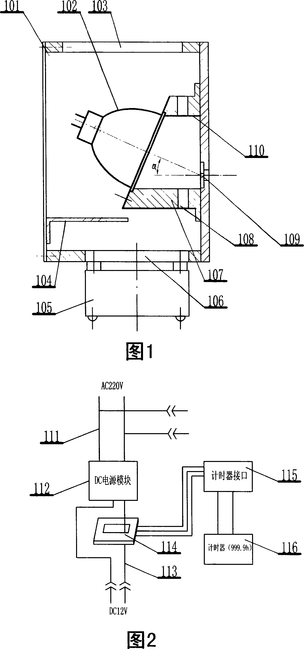
[0019] Referring to Fig. 1, the high-brightness light projector constant light source device of the present invention has a light source emitting box 101, and the front wall of the box is provided with a light source exit hole 109, and a lamp holder 107 is fixedly installed in the front wall, the lamp holder The central portion of 107 is provided with an optical channel 110 , and several cooling holes 108 communicating with the central optical channel 110 are provided on its peripheral wall. The end surface of the lamp holder 107 facing the light source is an inclined surface, the light source lamp 102 is installed obliquely on the inclined surface, and the focusing surface of the spotlight cover on it faces the light channel, and is buckled and connected with the lamp holder 107 . The light source lamp 102 adopts a halogen tungsten bulb, and the spotlight cover adopts an ellipsoidal cover. The angle α between the light axis of the light source lamp 102 and the exit light axis ...


PUM


Abstract

The invention relates to a constant light supply of high-brightness light projector used in optical plating detector. The invention is characterized in that the front wall the injecting box of light supply is fixed with a lamp base whose center is arranged with light channel; the base is arranged with a light supply lamp with collecting lamp cover; the collecting face of the cover is toward to the light channel and connected with the lamp base; the light supply lamp via wires is respectively connected with the power constant controller and the timer of light supply lamp; the front wall of the box is arranged with the light supply outlet; the side wall is arranged with the wind inlet and radiation outlet while the wind inlet is mounted with a fan. The invention can generate constant high-brightness strong light supply with high stability. And it can automatically control the apply time of light supply lamp.

Description

technical field [0001] The invention belongs to the field of optical technology, in particular to a constant light source device for a high-brightness light projector used in an optical coating monitoring system. Background technique [0002] In the optical vacuum coating monitoring process, the light source is the basis for generating the film thickness signal. It modulates and splits the light emitted by the light source part of the light projector, projects it onto the comparison sheet, and then generates the film thickness optical signal through the reflection of the comparison sheet. In this process, the light source is required to emit light that can provide high brightness and stable light source. In the prior art, the light source part of the light projector usually adopts an incandescent bulb placed flatly or vertically in the light source box, and some of them place a plane or curved reflector behind the incandescent bulb to enhance the brightness of the emitted li...

Claims


Application Information

Patent Timeline
Patent Type & Authority Applications(China)
IPC IPC(8): F21S2/00F21V3/02F21V29/00F21V29/02F21V23/00H05B37/02F21V29/50F21V29/83
CPCY02B20/42Y02B20/40
Inventor 菊池和夫赵升林党亚军张兰杨育兴
Owner HENAN COSTAR GRP CO LTD
Why Eureka
Try Eureka