Cooler
a cooling device and cooling technology, applied in the field of cooling devices, can solve the problems of lowering the cooling performance of the power module, large heat generation problem in the power module, etc., and achieve the effect of suppressing the lowering of the cooling performance, reducing the cooling performance of the cooler, and reducing the cooling performan
- Summary
- Abstract
- Description
- Claims
- Application Information
AI Technical Summary
Benefits of technology
Problems solved by technology
Method used
Image
Examples
embodiment 1
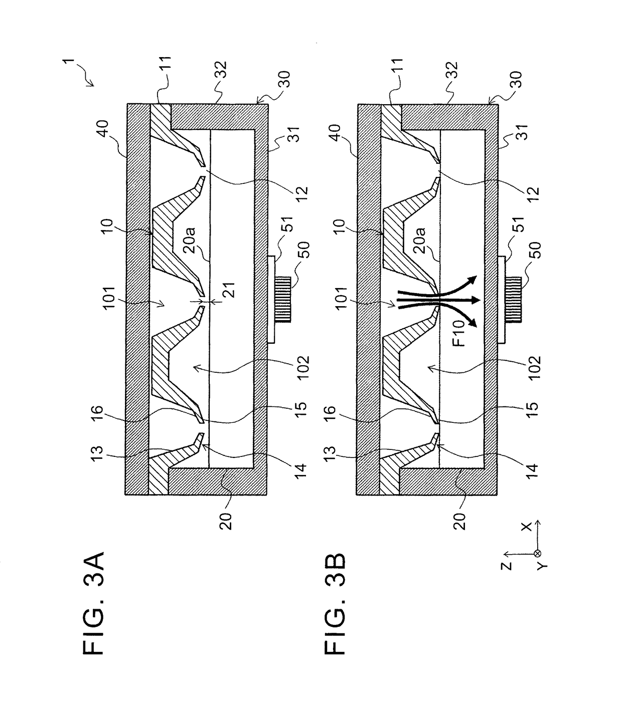
[0055]In a similar way to FIGS. 4A and 4B, a nozzle tip end 14 includes: a locally thin portion 19; and a pressure receiving portion 16. In Embodiment 1, the region of the nozzle tip end 14, which has a length of 0.3 mm or more from the opening end, is defined as the thin portion, and meanwhile, in this embodiment, a part of the nozzle tip end 14 is locally defined as the thin portion 19 that has low rigidity. For example, the locally thin portion 19 has a thickness of 1 mm or less, and may be separated from the opening end by 0.3 mm or more. In this case, the locally thin portion 19 is thinner than a flow passage wall 13, and is thinner than a peripheral portion of a coolant supply hole 12 (note: in FIGS. 5A and 5B, since the flow passage wall 13 is partially illustrated, an upper portion thereof is illustrated to be thinner; however, the upper portion is actually thicker). Note that a plurality of the locally thin portions 19, which are locally defined, may be formed. Furthermore,...
embodiment 3
[0059]FIGS. 6A and 6B are enlarged cross-sectional views of a vicinity of each of nozzle tip ends of a cooler according to FIG. 6A shows a state of the nozzle 10 before the coolant is flown therethrough, and FIG. 6B shows a state of the nozzle 10 when the coolant is flown therethrough.
[0060]In Embodiments 1 and 2, the nozzle tip end and the nozzle member are made of the single material integrally with each other. Meanwhile, in Embodiment 3, the nozzle tip end 14 is formed of a tip end member 17 separate from the nozzle member 11. In particular, rigidity of a material of the tip end member 17 is set lower than that of a material of the nozzle member 11. For example, the nozzle member 11 is made of resin, and the tip end member 17 is made of rubber. The resin is PPS or the like, and the rubber is nitrile or silicon rubber or the like. The tip end member 17 may be pasted onto the nozzle member 11 by thermocompression bonding or the like. Furthermore, an inflow passage 101-side surface...
embodiment 4
[0064]FIGS. 7A, 7B and 7C are enlarged cross-sectional views of a vicinity of each of nozzle tip ends of the cooler according to FIG. 7A shows a state, of the nozzle 10 before the coolant is flown therethrough, FIG. 7B shows a state of the nozzle 10 when the coolant is flown therethrough, and FIG. 7C shows a pressure receiving member when the coolant is ejected.
[0065]In Embodiment 3, the nozzle tip end 14 is formed of the tip end member 17. Meanwhile, in this embodiment, a pressure receiving member 18 (second tip end member) that serves as the pressure receiving portion 16 is further provided in a region (tip end peripheral portion) between an opening portion of the coolant supply hole 12 and the tip end member 17 (first tip end member). In a similar way to Embodiment 3, the nozzle member 11 is made of resin, and the tip end member 17 is made of rubber. Moreover, the pressure receiving member 18 is made of resin or metal. For example, the resin is PPS or the like, and the metal is ...
PUM
 Abstract
Description
Claims
Application Information
 - R&D
- Intellectual Property
- Life Sciences
- Materials
- Tech Scout
- Unparalleled Data Quality
- Higher Quality Content
- 60% Fewer Hallucinations
Browse by: Latest US Patents, China's latest patents, Technical Efficacy Thesaurus, Application Domain, Technology Topic, Popular Technical Reports.
© 2025 PatSnap. All rights reserved.Legal|Privacy policy|Modern Slavery Act Transparency Statement|Sitemap|About US| Contact US: help@patsnap.com


