
Ion generator

a generator and ion technology, applied in the field of ion generators, can solve the problems of difficult to discharge the target sufficiently, liable to occur corona discharge, etc., and achieve the effect of improving the neutralization efficiency and increasing the amount of air ions

Active Publication Date: 2018-12-25
KOGANEI
View PDF22 Cites 0 Cited by
  • Summary
  • Abstract
  • Description
  • Claims
  • Application Information

AI Technical Summary

Benefits of technology

[0006]There is a technique of grounding the counter electrode via high resistance so that the air ions generated by the discharge electrode are not captured by the counter electrode. In this configuration, when voltage is applied to the discharge electrode, the air ions are generated by the discharge. At the same time, the capture of the air ions to the counter electrode starts. Electric current is generated by flowing of the adsorbed air ions to the counter electrode. For that reason, the potential of the counter electrode rises. As a result, the electric field intensity between the discharge electrode and the counter electrode decreases. Moreover, the air ions generated by the discharge are separated from the discharge electrode, and are easily conveyed to the target.
[0008]The present invention is made in view of the above-described circumstances, and an object thereof is to provide an ion generator that is able to increase a conveyance amount of ion without affecting the generation amount of air ions.
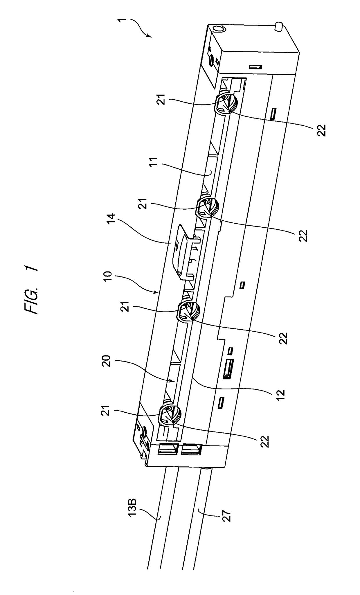
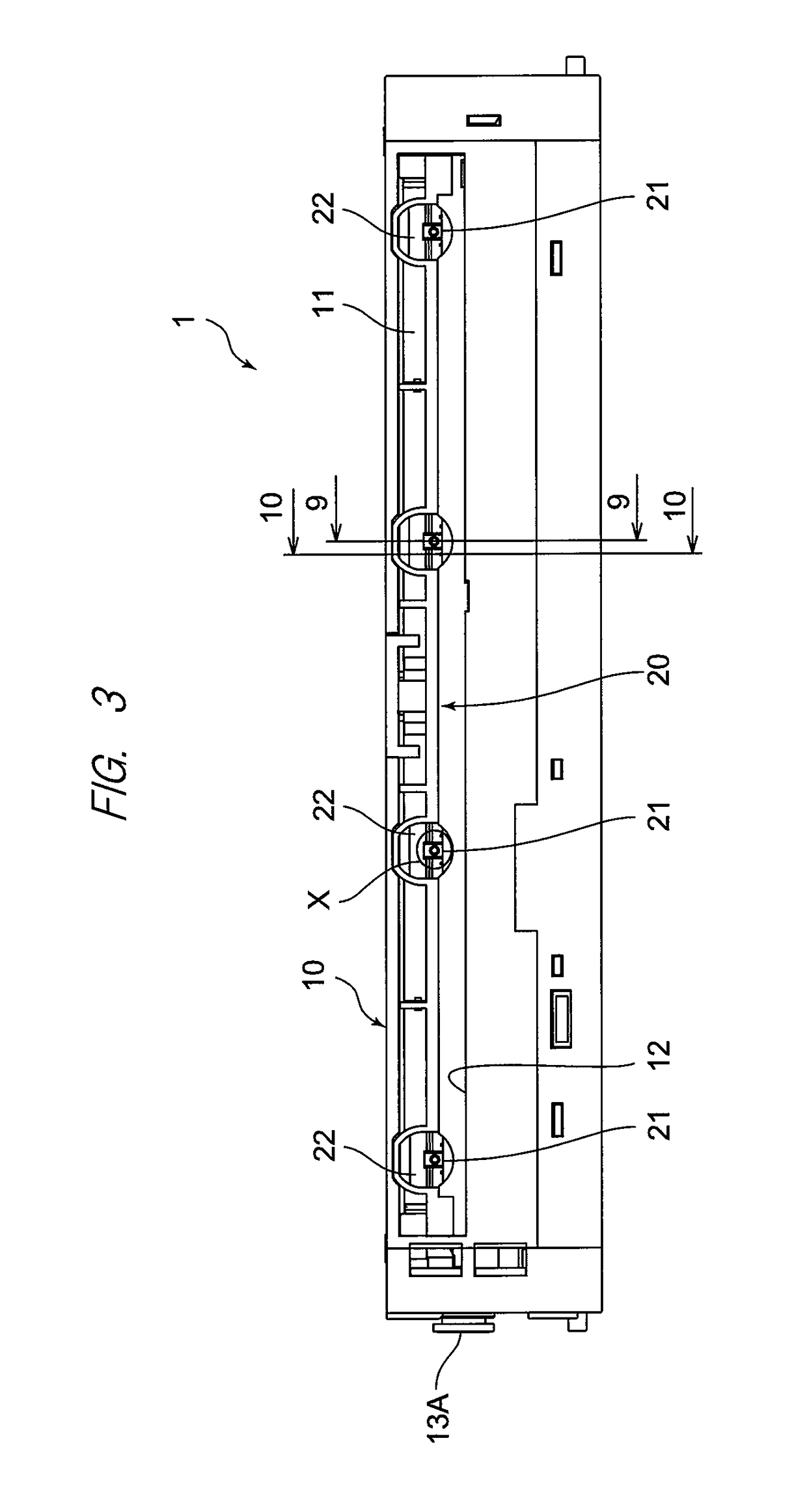
[0016]In the ion generator according to the present invention, since the counter electrode is located on the rear side by a predetermined distance from the discharge tip of the discharge electrode, an amount of the generated air ions being adsorbed to the counter electrode decreases, therefore the discharge becomes stable and a conveyance amount of air ions also increases. In addition, the balance between positive air ions and negative air ions to be generated is satisfactory. Therefore, neutralization efficiency is improved.

Problems solved by technology

And, as a distance between the discharge electrode and the counter electrode is short, the corona discharge is liable to occur.
In some cases, a balance between negative air ions and positive air ions to be generated, that is, an ion balance is degraded, which makes it difficult to sufficiently discharge the target.

Method used


Image

  • Ion generator
  • Ion generator
  • Ion generator

Examples


Embodiment Construction

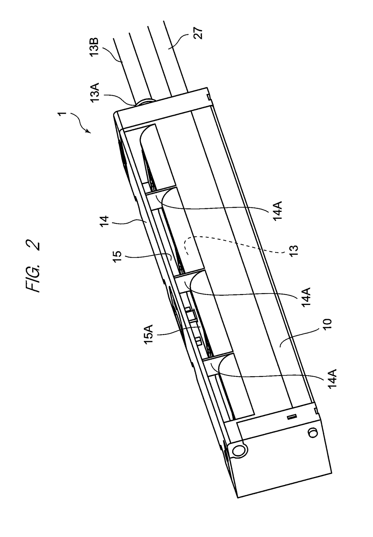
[0034]Hereinafter, one embodiment of an ion generator according to the present invention will be described in detail with reference to the drawings. In addition, a vertical direction, a lateral direction (width direction), and a depth direction used in the following description refer to directions as viewed from the front side, when a front side of FIG. 1 is assumed to be a front (surface side). In the embodiment described below, as an example of the ion generator, a wide type product that blows out the generated air ions from an oblong blow-off opening will be described. However, the present invention is not limited thereto.

[0035]In the description of the present specification, there is air of three different types. In other words, one is “ejected air”. Another is “outside air”. The other is “assist air”. The “ejected air” is air that is supplied to an air supply port 13A (see FIG. 8) of an ion generator 1 from a compressor and is discharged from a first air discharge port 16 (see ...


PUM


Abstract

Provided is an ion generator that sends out air ions generated by applying high voltage between a discharge electrode and a counter electrode, the ion generator including: an air discharge port provided in a housing of the ion generator to send ejected air toward a region between the discharge electrode and the counter electrode; and an opening portion configured to discharge the generated air ions by the ejected air, in which the counter electrode is positioned on an upstream side of the flow of the ejected air with respect to the discharge electrode.

Description

CROSS-REFERENCE TO RELATED APPLICATIONS[0001]This application is entitled to the benefit of and incorporates by reference subject matter disclosed in International Patent Application No. PCT / JP2014 / 079858 filed on Nov. 11, 2014 and Japanese Patent Application No. 2013-240173 filed on Nov. 20, 2013, the contents of which are hereby incorporated by reference into this application.TECHNICAL FIELD[0002]The present invention relates to an ion generator that blows positive air ions and negative air ions generated by corona discharge to a charged object (hereinafter, referred to as “target”), thereby neutralizing the charge of the target.BACKGROUND ART[0003]In order to discharge the target by blowing the air ions to the target charged with static electricity, an ion generator also referred to as an ionizer or a static eliminator is used. The ion generator used in a production line configured to perform manufacturing and assembly of electronic components is used to remove the static electri...

Claims


Application Information

Patent Timeline
Patent Type & Authority Patents(United States)
IPC IPC(8): H01T23/00H01T19/00H01T19/04H05F3/06
CPCH05F3/06H01T23/00H01T19/04H01T19/00
Inventor FUKADA, YOSHINARIONEZAWA, KAZUYOSHITAKAHASHI, YUJI
Owner KOGANEI
Learn More