Untuned resonance traced gas sensing

a gas sensing and resonance technology, applied in the field of gas sensing, can solve problems such as difficulty in field deployment of such sensors

Inactive Publication Date: 2019-01-01
INT BUSINESS MASCH CORP
View PDF8 Cites 7 Cited by
  • Summary
  • Abstract
  • Description
  • Claims
  • Application Information

AI Technical Summary

Problems solved by technology

However, long transmission paths correspond to large instruments, which can make it difficult to deploy such sensors in the field.

Method used


Image

  • Untuned resonance traced gas sensing
  • Untuned resonance traced gas sensing
  • Untuned resonance traced gas sensing

Examples


Embodiment Construction

[0014]Embodiments of the present invention provide sensitive gas sensing using low-loss waveguide sensors that have relatively short transmission paths. An optical resonator ring is used as the sensing element, with a path length less than a tenth of what would be needed to provide a similar sensitivity with a linear waveguide.

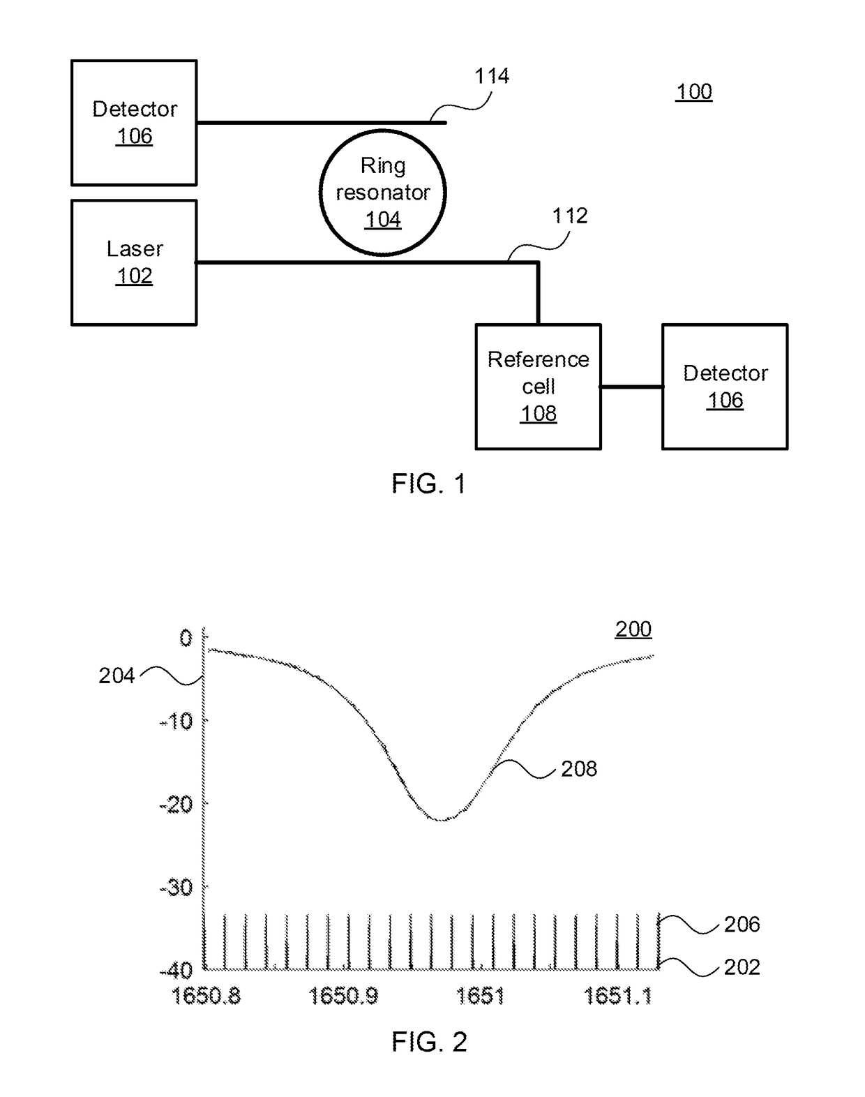
[0015]Referring now to FIG. 1, a block diagram of the sensing apparatus 100 is shown. A laser 102 generates an optical signal and launches the optical signal on an input waveguide 112. It is specifically contemplated that the waveguide 112 may be formed from a low-loss material, characterized by small, but non-zero, amounts of power being lost as the signal propagates. The waveguide 112 may be formed from silicon nitride waveguides fabricated on top of a silicon dioxide lower cladding. The role of the top cladding is filled by the gas in either the sensing region 104 or reference cell region 108. To increase the electric field overlap with the gas, a silicon n...


PUM

PropertyMeasurementUnit
circumferenceaaaaaaaaaa
widthaaaaaaaaaa
widthaaaaaaaaaa

Abstract

Methods and systems for detecting a gas or liquid in an environment include measuring a reference signal at each of a set of wavelengths by passing a signal at each wavelength through a reference cell having a gas or liquid to be detected. A sensing signal is measured at each of the plurality of wavelengths by coupling each wavelength to a ring resonator in the environment. A set of wavelengths that correspond to an absorption curve of the gas or liquid to be detected is determined. A concentration of the gas or liquid to be detected in the environment is determined based on amplitudes of the sensing signal at each of the set of wavelengths.

Description

STATEMENT REGARDING FEDERALLY SPONSORED RESEARCH OR DEVELOPMENT[0001]This invention was made with Government support under Contract No.: DE-AR0000540 awarded by Department of Energy. The Government has certain rights in this invention.BACKGROUNDTechnical Field[0002]The present invention generally relates to gas sensing and, more particularly, methods and structures for gas sensing that use optical resonance yet do not need to be tuned.Description of the Related Art[0003]Existing gas sensors based on optical signals in waveguides need extremely long transmission paths to be made practical. However, long transmission paths correspond to large instruments, which can make it difficult to deploy such sensors in the field.SUMMARY[0004]A method for detecting a gas or liquid in an environment includes measuring a reference signal at each of a set of wavelengths by passing a signal at each wavelength through a reference cell having a gas or liquid to be detected. A sensing signal is measured...

Claims


Application Information

Patent Timeline
Patent Type & Authority Patents(United States)
IPC IPC(8): G01N21/25G01N21/27G01N33/00G01N21/31G02B6/293
CPCG01N21/255G01N21/27G01N21/31G01N33/0047G02B6/29338G01N33/0022G01N2201/0873G01N21/7746
Inventor ORCUTT, JASON S.
Owner INT BUSINESS MASCH CORP
Why Eureka
Try Eureka