Selective peripheral vision filtering in a foveated rendering system

a peripheral vision and filtering technology, applied in the field of digital graphics, can solve the problems of human vision, foveated rendering techniques, and common foveated rendering techniques

Active Publication Date: 2019-01-01
SONY COMPUTER ENTERTAINMENT INC
View PDF79 Cites 16 Cited by
  • Summary
  • Abstract
  • Description
  • Claims
  • Application Information

AI Technical Summary

Problems solved by technology

Although a foveated rendering process can reduce system overhead and power usage, problems can arise as a result of the nature of human vision.
Foveated rendering techniques typically reduce the resolution or visual fidelity of peripheral portions of images delivered to a display, e.g., an HMD.
Reducing resolution in peripheral region may increase contrast, which can lead to visual artifacts, such as aliasing and scintillation of pixels.
Unintended excitation of the viewer's peripheral vision system due to such aliasing and scintillation (sometimes referred to as pixelation) is distracting.
The problem with the aforementioned filtering approach is that it can mask objects in the user's periphery that are important.
However, rendering geometry onto displays, especially high FOV view planes, can be very inefficient and result in significant latency and performance issues.
These issues can cause the displayed frame rate to drop below desired levels, creating a jarring, non-immersive experience for a user, in addition to potentially inducing motion sickness in a user immersed in a VR environment.
Additionally, regions of the display near the edge of the screen, or regions which the user is not viewing, or not likely to view, hold much less meaningful information than regions near the center or to which a user's attention is currently directed.
Foveated rendering may be limited by the capabilities of the gaze tracking system.
In systems and devices that utilize eye tracking, errors in eye tracking and associated latencies in tracking, as well as the inability to track eye state information, cause these systems to need a much greater radius of high resolution on the display than is theoretically needed to preserve the high fidelity for the user.
This issue is particularly prevalent in virtual reality systems, wherein performance is dependent on screen resolution.
In such systems, high levels of rendering are required in order to maintain an ideal resolution, however, much of rendering performed is unnecessary since a user's eyes only focus on a small part of the screen.
In general terms, the fixed sampling rate or exposure time of the gaze tracking system may lead to a greater error between the determined future position and the actual future position for a user with larger values of rotational velocity and acceleration.
Fewer pixels available on the screen generally means that the minimum vertex density or pixel resolution value cannot be made too small.
If the foveated rendering is specific to what the user is looking at, images with foveated rendering could be very confusing to spectators.

Method used


Image

  • Selective peripheral vision filtering in a foveated rendering system
  • Selective peripheral vision filtering in a foveated rendering system
  • Selective peripheral vision filtering in a foveated rendering system

Examples


Embodiment Construction

[0020]Although the following detailed description contains many specific details for the purposes of illustration, anyone of ordinary skill in the art will appreciate that many variations and alterations to the following details are within the scope of the invention. Accordingly, the illustrative implementations of the present disclosure described below are set forth without any loss of generality to, and without imposing limitations upon, the claimed invention.

INTRODUCTION

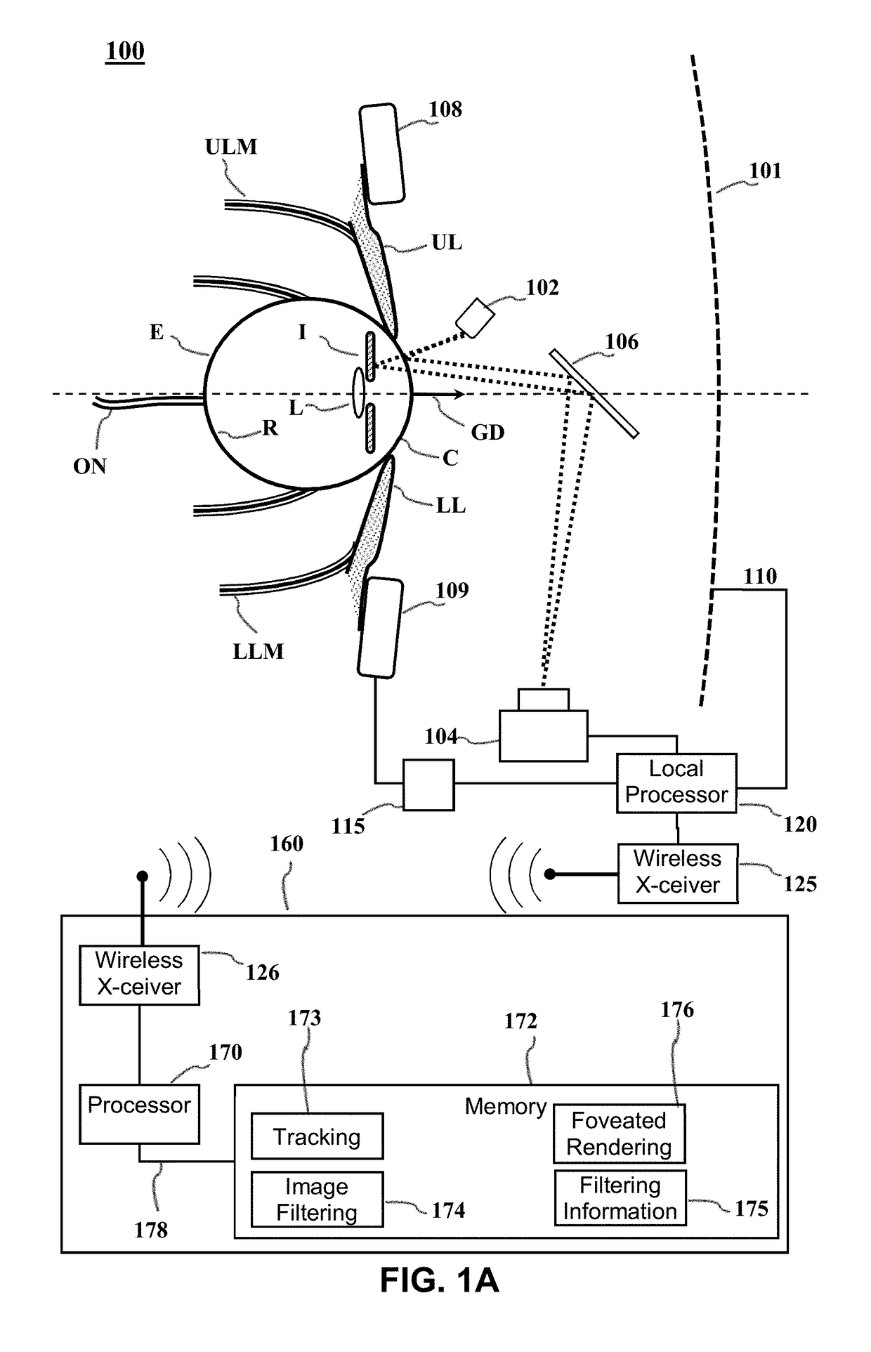
[0021]Although a foveated rendering process can reduce system overhead and power usage, problems can arise as a result of the nature of human vision. Foveated rendering techniques typically reduce the resolution or visual fidelity of peripheral portions of images delivered to a display, e.g., an HMD. Human peripheral vision is finely tuned to contrast and motion detection. Reducing resolution in peripheral region may increase contrast, which can lead to visual artifacts, such as aliasing and scintillation of pixel...


PUM


Abstract

Gaze tracking data representing a viewer's gaze with respect to one or more images presented to the viewer is used to generate foveated image data representing one or more foveated images characterized by a higher level of detail within one or more regions of interest and a lower level of detail outside the regions of interest. The image data for portions outside the one or more regions of interest is selectively filtered to reduce visual artifacts due to contrast resulting from the lower level of detail before compositing foveated images for presentation.

Description

FIELD OF THE DISCLOSURE[0001]Aspects of the present disclosure are related to digital graphics. In particular, the present disclosure is related to varying the quality of imagery presented to the peripheral vision of a viewer.BACKGROUND[0002]Graphical display devices having a wide field of view (FOV) have been developed. Such devices include head mounted display (HMD) devices. Typically in an HMD device, a small display device is worn on a user's head. The display device has a display optic in front of one eye (monocular HMD) or each eye (binocular HMD). An HMD device typically includes sensors that can sense the orientation of the device and change the scene shown by the display optics as the user's head moves. Conventionally, most stages of rendering scenes for wide FOV displays are performed by planar rendering where all parts of the screen have the same number of pixels per unit area.[0003]However, rendering for virtual reality (VR) programs, which is often performed in conjunct...

Claims


Application Information

Patent Timeline
Patent Type & Authority Patents(United States)
IPC IPC(8): G06T5/00G06T17/20G06F3/03G06F1/16G02B27/01G06F3/01
CPCG06T5/00G02B27/0179G06F1/163G06F1/1694G06F3/011G06F3/012G06F3/013G06F3/0304G06T17/20G02B27/017G06T2210/36G02B2027/014G02B2027/0118G02B2027/0147G02B2027/0187G06T2207/20024G06T2207/20192G06T2207/20221G06V40/18
Inventor STAFFORD, JEFFREY ROGERYOUNG, ANDREW
Owner SONY COMPUTER ENTERTAINMENT INC
Why Eureka
Try Eureka