Piezoelectric MEMS microphone

a microphone and piezoelectric technology, applied in the field of piezoelectric mems microphones, can solve the problems of high cost, inability to mount to a printed circuit board, and the inability to use mems capacitive microphones, which are often used in cell phones,

Active Publication Date: 2019-01-01
RGT UNIV OF MICHIGAN +1
View PDF37 Cites 13 Cited by
  • Summary
  • Abstract
  • Description
  • Claims
  • Application Information

AI Technical Summary

Problems solved by technology

However, each of these more ubiquitous technologies has its own disadvantages.
For standard ECMs, they typically cannot be mounted to a printed circuit board using the typical lead-free solder processing commonly used on all other microchips attached to the board.
MEMS capacitive microphones, which are often used in cell phones, are relatively expensive due at least in part to the use of an application-specific integrated circuit (ASIC) that provides readout circuitry for the microphone.
Conventional microphones additionally suffer from high noise floors due to the limited back cavity volume of the increasingly smaller microphones.
As taught by the prior art, noise levels are affected by the back cavity stiffness of the microphone.
While back cavity volume maximization to near-infinite volumes is feasible in larger microphone systems, this type of maximization cannot be realized in smaller microphone systems, particularly in microphones smaller than 50 mm3, where any increase in volume comes at a premium.
Without the ability to minimize back cavity stiffness, conventional microphone designs either ignore the effects of the back cavity volume on microphone performance, or account for the back cavity stiffness as a parasitic stiffness.

Method used


Image

  • Piezoelectric MEMS microphone
  • Piezoelectric MEMS microphone
  • Piezoelectric MEMS microphone

Examples


Embodiment Construction

[0049]The description that follows is directed to various embodiments of a piezoelectric MEMS microphone that meets an optimization criteria which can be determined in one or more of the different manners described below.

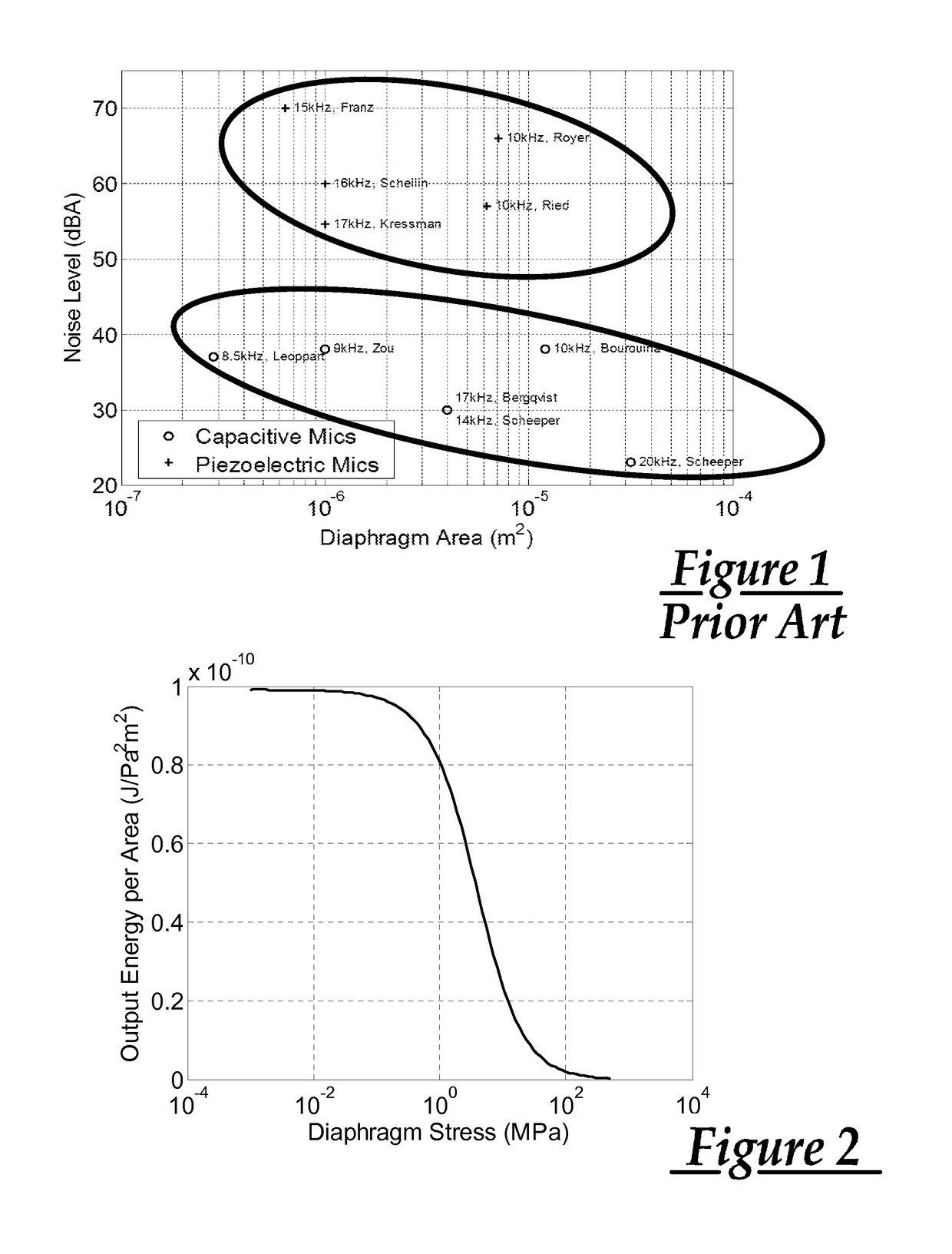
[0050]Typical piezoelectric MEMS microphones are designed so as to optimize sensitivity of the microphone, and this is at least partially responsible for the increased noise floors noted above for these devices. As described below, by optimizing the ratio of output energy to sensor area for a given input pressure, bandwidth, and piezoelectric material, a piezoelectric MEMS microphone can be constructed that has sufficient sensitivity for typical applications along with a noise floor similar to that of capacitive MEMS microphones. This approach is valid for films of good quality. However, as the film is reduced in thickness, the film quality will degrade. This factor can be accounted for with an alternative approach described herein which utilizes a calculated optimi...


PUM


Abstract

A microphone including a casing having a front wall, a back wall, and a side wall joining the front wall to the back wall, a transducer mounted to the front wall, the transducer including a substrate and a transducing element, the transducing element having a transducer acoustic compliance dependent on the transducing element dimensions, a back cavity cooperatively defined between the back wall, the side wall, and the transducer, the back cavity having a back cavity acoustic compliance. The transducing element is dimensioned such that the transducing element length matches a predetermined resonant frequency and the transducing element width, thickness, and elasticity produces a transducer acoustic compliance within a given range of the back cavity acoustic compliance.

Description

CROSS-REFERENCE TO RELATED APPLICATIONS[0001]This application claims the benefit of U.S. Provisional Application No. 61 / 779,892 filed 13 Mar. 2013 and is a continuation-in-part of U.S. application Ser. No. 13 / 963,661 filed 9 Aug. 2013, which is a continuation of U.S. application Ser. No. 12 / 495,195 filed 30 Jun. 2009, now U.S. Pat. No. 8,531,088, which claims the benefit of U.S. Provisional Application No. 61 / 076,928 filed 30 Jun. 2008. The entire contents of each of these prior applications are hereby incorporated by reference.TECHNICAL FIELD[0002]This invention relates generally to piezoelectric microphones and, in particular, to piezoelectric MEMS microphones and design techniques for constructing such microphones to meet the requirements of a particular end use application.BACKGROUND[0003]The rise of microelectromechanical systems (MEMS) technology has enabled the development of acoustic transducers such as microphones using silicon-wafer deposition techniques. Microphones fabri...

Claims


Application Information

Patent Timeline
Patent Type & Authority Patents(United States)
IPC IPC(8): H04R17/02H01L41/083H01L41/187H01L41/113B81B3/00H04R17/00
CPCH01L41/083B81B3/0021H01L41/1132H01L41/1136H01L41/187H04R17/00H04R17/02H01L41/1138H04R2201/003B81B2201/0257B81B7/0032B81B7/02B81B2203/0127B81B2203/0315B81B2203/04B81B2207/09H10N30/50H10N30/302H10N30/306H10N30/308H10N30/853
Inventor GROSH, KARLLITTRELL, ROBERT J.
Owner RGT UNIV OF MICHIGAN
Why Eureka
Try Eureka