Electric tool

a technology of electric tools and housings, applied in the field of electric tools, can solve the problems of inability to control the rotation of the motor, stop the motor, and internal blockage, and achieve the effects of preventing water splashing on the electronic elements mounted in the housing, reducing the risk of damage, and reducing the cost of maintenance and replacemen

Active Publication Date: 2019-01-08
KOKI HLDG CO LTD
View PDF22 Cites 6 Cited by
  • Summary
  • Abstract
  • Description
  • Claims
  • Application Information

AI Technical Summary

Benefits of technology

[0009]The invention is provided in consideration of the background. The purpose of the invention is to provide an electric tool with a configuration as follows: namely, the electric tool prevents anomalies in motor rotation due to dust and moisture sucked in together with cooling wind, and is configured such that rotational position detection operations and switch operations are not affected.
[0012]According to other characteristics of the invention, the housing is formed of a non-magnetic material, and, as a divided configuration, sets a space to be a seal structure, or is in a shape of a container having an opening part and covered by a solidifiable water-resistant material, such as silicon, inside the housing, so as to configure a water-resistant and dust-resistant structure. Accordingly, splashing of water onto electronic elements mounted in the housing can be prevented. Besides, the controller and the magnetic detection unit are configured on the circuit substrate disposed in the housing as a water resistant and dust resistance structure together with other electronic elements. Therefore, an electric tool having a higher durability and reliability is provided. Moreover, since the housing is formed of synthetic resin or non-magnetic metal, the housing hardly has an influence on a magnetic field generated by a magnetic body. Therefore, the magnetic detection unit capable of being accommodated in the housing.
[0013]According to another characteristic of the invention, the casing is in a cylindrical shape, the ventilating window for sucking the external gas is disposed on a rear side in an axial direction, and a ventilating window for discharging air is disposed on a front side of the casing. The casing has a bearing holding part holding a bearing providing axial support to the rotation shaft of the motor, and the magnetic body and the bearing held in a state of being separated from the wind generated by the cooling fan by connecting the bearing holding part and the housing. Moreover, since a cover member is disposed between the bearing holding part and the stator to isolate the wind generated by the cooling fan and an internal space of the motor, the cooling wind is prevented from entering the inside of the motor, thereby eliminating damages to the motor caused by the iron powder or moisture entering the casing. Furthermore, since a wall surface of the housing is disposed between the magnetic body and the magnetic detection unit, dust resistance on the side of the magnetic body and dust resistance on the side of the magnetic detection unit are independent from each other.

Problems solved by technology

However, since a powerful permanent magnet is used in the rotor part, if iron powder enters the inside of the motor, the iron powder may be attached to the magnet without being discharged, thereby forming internal blockage.
However, if the iron powder is attached to the sensor magnet 114, the iron powder may remain attached, and a magnetic anomaly may occur, making it unable to control the rotation of the motor 106, which may possibly stop the motor 106.

Method used


Image

  • Electric tool
  • Electric tool
  • Electric tool

Examples


embodiment 1

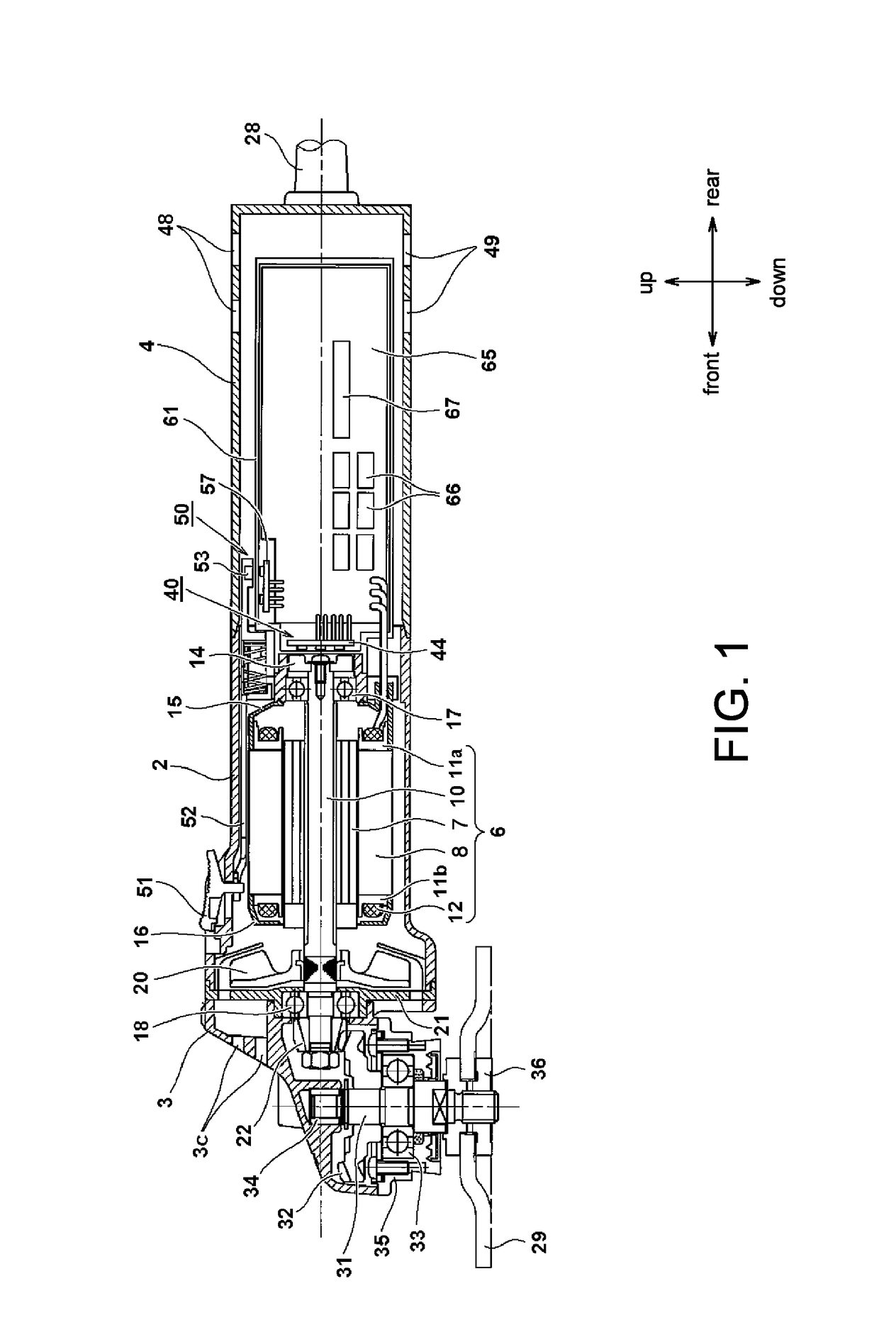
[0029]In the following, the embodiments of the invention are described with reference to the accompany drawings. In addition, in the following figures, components having the same functions are noted with the same reference numerals, and repeated descriptions are omitted. Moreover, in the description, directions of front, rear, left, right, up, and down are described based on the directions in the drawings.

[0030]FIG. 1 is a top view illustrating an electric tool 1 according to an embodiment of the invention. Here, as an example of the electric tool 1, an operating device connected to a rotation shaft of a motor is shown as a grindstone, for example, indicating that the device is a disc grinder. A casing (outer frame) of the electric tool 1 includes three main sections, namely a gear box 3 accommodating a power transmission mechanism, a motor casing 2 accommodating a motor 6, and a rear cover 4 installed behind the motor casing 2 and accommodating electronic elements. In this embodime...

embodiment 2

[0072]FIG. 13 is a partial cross-sectional view illustrating a structure of an electric tool having a labyrinth mechanism according to a second embodiment of the invention. In the second embodiment, the structure of the cover member on the front side of the motor 6 is changed, so as to further facilitate an effect of labyrinth. Here, a non-contact seal structure as follows is configured. Namely, the balance weight is not disposed. Instead, a windshield plate 86 and a cover member 85 are disposed as a balance member. In addition, a plurality of sections of concave and convex gaps are disposed between the windshield plate 86 and the cover member 85, so as to increase a channel resistance by extending a total length of the fine separation from outside to inside and substantially block an air flow from outside to inside. The windshield plate 86 is formed with an installation part 86d. The installation part 86d is formed in a cylindrical shape on a periphery of a through hole on an inner...


PUM


Abstract

An electric tool is provided. The electric tool prevents anomalies in motor rotation due to dust and moisture sucked in together with a cooling wind, and is configured such that rotational position detection operations and switch operations are not affected. In the electric tool which drives a brushless DC motor using a controller, a magnetic body for rotational position detection is provided on a rotation shaft which can rotate integrally with a rotor, Hall ICs are provided to detect the rotational position of the magnetic body and output a position signal to the controller, and the magnetic body and the Hall ICs mounted on a substrate are arranged in a region isolated from the wind path of the cooling wind generated by rotation of a cooling fan. The Hall ICs are accommodated in a housing filled with resin.

Description

CROSS-REFERENCE TO RELATED APPLICATION[0001]This application is a 371 application of the international PCT application serial no. PCT / JP2015 / 067724, filed on Jun. 19, 2015, which claims the priority benefit of Japan application no. 2014-135465, filed on Jun. 30, 2014. The entirety of each of the abovementioned patent applications is hereby incorporated by reference herein and made a part of this specification.BACKGROUND OF THE INVENTION[0002]Field of the Invention[0003]The invention relates to an electric tool using a brushless motor, and particularly provides an electric tool capable of suppressing permeation of moisture or dust into an internal space of a motor, a bearing part, or a control circuit substrate, thereby increasing a device lifetime.[0004]Description of Related Art[0005]Currently, electric tools using a brushless direct current (DC) motor and a controller, such as a microcomputer, to control rotation of a motor at a high precision are already known. The brushless DC m...

Claims


Application Information

Patent Timeline
Patent Type & Authority Patents(United States)
IPC IPC(8): B25F5/00B24B23/02B24B49/10
CPCB25F5/008B24B23/02B25F5/00B24B49/10B24B23/028
Inventor TAKEDA, YUUKI
Owner KOKI HLDG CO LTD
Why Eureka
Try Eureka