Al technical title is built by PatSnap Al team. It summarizes the technical point description of the patent document.
a remote control and control technology, applied in the field of remote control, can solve the problems of irreversible trigger action of the controlled equipment, major constraint in security, and unsatisfactory solutions for industrial environments, and achieve the effect of simple learning
Inactive Publication Date: 2019-01-08
SIATECH
View PDF6 Cites 1 Cited by
Summary
Abstract
Description
Claims
Application Information
AI Technical Summary
This helps you quickly interpret patents by identifying the three key elements:
Problems solved by technology
Method used
Benefits of technology
[0013]This solution solves the problem of operational safety, in particular, relating to the interferences caused by unintentional movements by the operator. It also enables a very intuitive utilization, requiring only a very simple learning, with a large number of orders that can be transmitted, with the operator having to act only to enable or disable the transmission of instructions otherwise continuously acquired by the movements of his / her hand, his / her arm or his / her forearm.
Problems solved by technology
These solutions are not completely satisfactory for use in industrial environments.
In such environments, security is a major constraint.
The involuntary or inappropriate pressing of a key irreversibly triggers an action by the controlled equipment that may be, at best, inappropriate, but sometimes hazardous.
In addition, remote control equipment is subjected to multiple stresses (shocks, sweat, dust, humidity, etc.).
The gloves disclosed in the prior art do not make it possible to fully solve these problems because they require the availability of a large number of sizes so that each operator can have a remote glove adapted to his / her morphology.
In addition, the gloves are subjected to high stresses that are less compatible with the integration of an electronic component.
Method used
Image
Click on the blue label to locate the original text in one second.
Reading with bidirectional positioning of images and text.
Examples
first exemplary embodiment
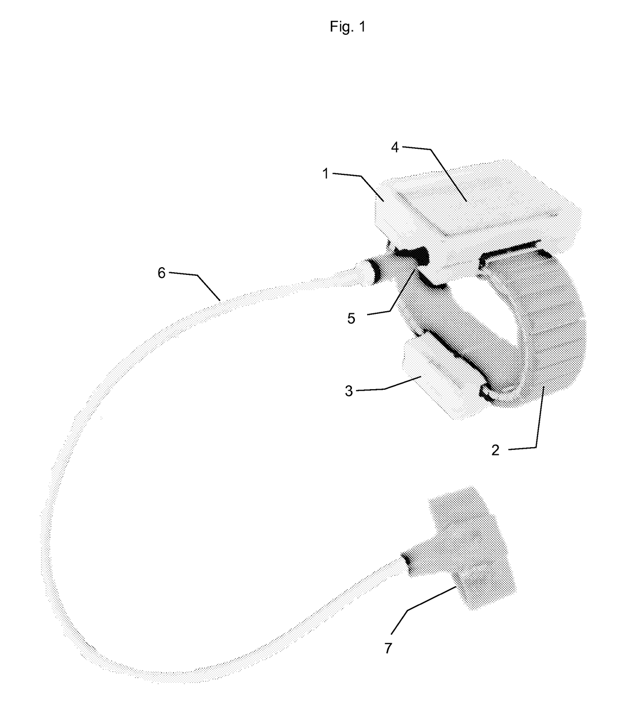
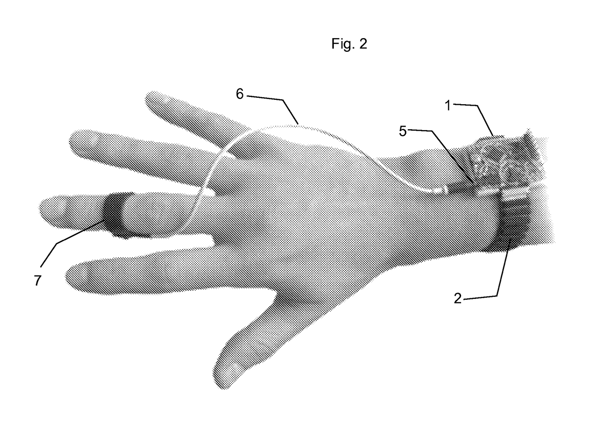
[0039]The non-limiting embodiment of the disclosure relates to a remote control of a bridge crane through the movements of the hand.
[0040]The equipment comprises a box 1 that, in the example described, can be fitted to a strap 2 through a reversible mechanical connection.
[0041]Such box 1 accommodates the electronic circuit comprising a micro-controller, an accelerometer, a battery and a battery charging pilot circuit. The upper part of the box 1 has a surface 4 associated with a contactor enabling the user to control a function of emergency stop of the controlled equipment.
[0042]The box 1 also has, on one of its side faces, a socket 5 having a double function:[0043]when not in use, it enables the connection of a connector for charging the battery built in the box 1.[0044]in use, it enables the connection of a cable 6 connecting the circuits of the box 1 and a digital contactor 7.
[0045]In the non-restrictive example described, this strap is provided with a second box 3 having a remot...
PUM
Abstract
The present disclosure relates to a remote control including an electronic circuit comprising means for detecting the position, orientation and movement of the hand and / or forearm such as an accelerometer, means for transmitting at radiofrequency a control signal calculated depending on the measured position, orientation and movement, and a means for fastening to the forearm of an operator, wherein the remote control further comprises a contactor able to be actuated by the interaction of two fingers, the contactor controlling the activation of the electronic circuit and the maintenance of the control signal until the action on the contactor is stopped, and a bearing surface associated with a contactor controlling an emergency stoppage of the controlled equipment.
Description
CROSS-REFERENCE TO RELATED APPLICATIONS[0001]This application is a national phase entry under 35 U.S.C. § 371 of International Patent Application PCT / FR2016 / 051374, filed Jun. 8, 2016, designating the United States of America and published as International Patent Publication WO 2016 / 207505 A1 on Dec. 29, 2016, which claims the benefit under Article 8 of the Patent Cooperation Treaty to French Patent Application Serial No. 1555737, filed Jun. 23, 2015, the disclosures of which are incorporated herein in their entireties by this reference.TECHNICAL FIELD[0002]The present disclosure relates to the field of remote controls, specifically of industrial equipment and, more particularly, to equipment such as lifting or handling equipment, especially gantry cranes, bridge cranes, cranes, lift trucks, pallet trucks, stackers, order pickers, truck-mounted winches, boat lift cranes, automatic logistics warehouses, as well as mobile machines, such as boat trailers / bridges, tunneling machines, on...
Claims
Application Information
Patent Timeline
Application Date:The date an application was filed.
Publication Date:The date a patent or application was officially published.
First Publication Date:The earliest publication date of a patent with the same application number.
Issue Date:Publication date of the patent grant document.
PCT Entry Date:The Entry date of PCT National Phase.
Estimated Expiry Date:The statutory expiry date of a patent right according to the Patent Law, and it is the longest term of protection that the patent right can achieve without the termination of the patent right due to other reasons(Term extension factor has been taken into account ).
Invalid Date:Actual expiry date is based on effective date or publication date of legal transaction data of invalid patent.