Heat shield and system with heat shield of this type

a heat shield and heat shield technology, applied in the field of heat shields, can solve the problems of increasing the space requirement of heat shields, heavy, and only offering limited insulating power, and achieve the effects of reducing density, increasing bending strength, and increasing elasticity

Active Publication Date: 2019-01-22
REINZ DICHTUNGS
View PDF16 Cites 0 Cited by
  • Summary
  • Abstract
  • Description
  • Claims
  • Application Information

AI Technical Summary

Benefits of technology

[0011]According to the invention, as the insulating material, hollow fibers are used at least partly, predominantly or even exclusively that have a tubular hollow, unfilled cross section at least in segments or over their entire length. The use of hollow fibers of this type has several decisive advantages compared to the prior art. As a result of the hollow space in the fibers, the insulating power, both in terms of thermal insulation as well as acoustic insulation, is better with an insulating layer of identical thickness than the insulating power of conventional materials. On the other hand, with similar insulating properties, this makes it possible to reduce the amount of material and the thickness of the insulating layer and thus to reduce the space required for the heat shield according to the invention. As a result of the hollow spaces in the fibers, the weight of the component is also reduced. Overall, when the hollow fibers according to the invention are used, the coefficient of thermal conduction of the insulating layer can be reduced from 0.4 W / mK for materials of the prior art to 0.2 W / mK, for example.
[0014]The hollow fibers in the insulating layer need not be all identical, but it is sufficient if they are similar or identical in terms of one or more properties. The insulating layer, in the longitudinal plane and / or at a right angle to the longitudinal plane, can also have two or more segments in which the hollow fibers are different in terms of a property. This option makes it possible to have particularly effective insulation in hot spots, i.e. areas in which a particularly large amount of heat is generated, for example by an accumulation of hollow fibers with a particularly large hollow proportion, compared to other areas that are subjected to lower thermal loads.
[0018]This invention can be implemented in particular by the use of glass fibers and / or silicate fibers. For example, the fibers can be produced using or from alkali-free aluminum borosilicate glass. The types of glass cited here, e.g. alkali-free aluminum borosilicate glass, can have an outside diameter of 10 to 12 μm with an inside capillary tunnel diameter between 5 and 6 μm. Glass fibers of this type have a higher bending strength than solid fibers, in spite of their approximately 40% lower density. Consequently, the fibers are more elastic and have a higher compression strength as well as higher specific strength, improved thermal and / or acoustic insulating properties and a lower thermal conductivity. The density can be, for example, 1.4 g / cm3 and the thermal conductivity 0.21 W / mK. If they are suitably connected to one another, the fiber material that is used for the insulating layer, which at least has a defined contour, is also self-supporting with many types of connections. For a particularly flexible configuration of the insulating layer, however, it is preferable if it has a filled material at least in sections, which is held in place, for example, by a layer of fibers connected with one another at the points in question. For this purpose, the self-supporting sections of the insulating layer, in particular sections of the insulating layer solidified with binder, can be in the form of shaped parts that have depressions or protuberances to hold the filled material. The shaping of the sheet metal layer with depressions, for example, can facilitate the realization of embodiments shaped in this manner.
[0019]To improve the stability of the insulating layer, the fibers can be needled, sewn, crocheted, woven or in the form of fleece, for example. Alternatively, they can be at least partly, predominantly or completely connected with one another by means of a binder, to give the insulating layer inherent stabilization.
[0021]Optionally, the insulating layer can also contain phase change materials. For this purpose, for example, phase change materials with phase change temperatures between 70 and 300° C., preferably between 80° C. and 200° C., can be used. Phase change materials of this type include, for example, paraffin, salt hydrates or eutectic salt hydrate mixtures, salts or eutectic salt mixtures or similar materials. As a result of the use of phase change materials, the areas of a component next to the heat shield, in particular the areas of a component surrounded by the heat shield or a component completely surrounded by the heat shield, for example, can be heated when an engine is started even more quickly than is possible with the use of the hollow fibers according to the invention. As the result of a rapid heating, for example of an internal combustion engine as the component, harmful emissions in the startup phase of the internal combustion engine are reduced.

Problems solved by technology

One disadvantage of all these heat shields is that they are heavy and offer only limited insulating power.
However, that also increases the space requirement for the heat shield.

Method used


Image

  • Heat shield and system with heat shield of this type
  • Heat shield and system with heat shield of this type
  • Heat shield and system with heat shield of this type

Examples


Embodiment Construction

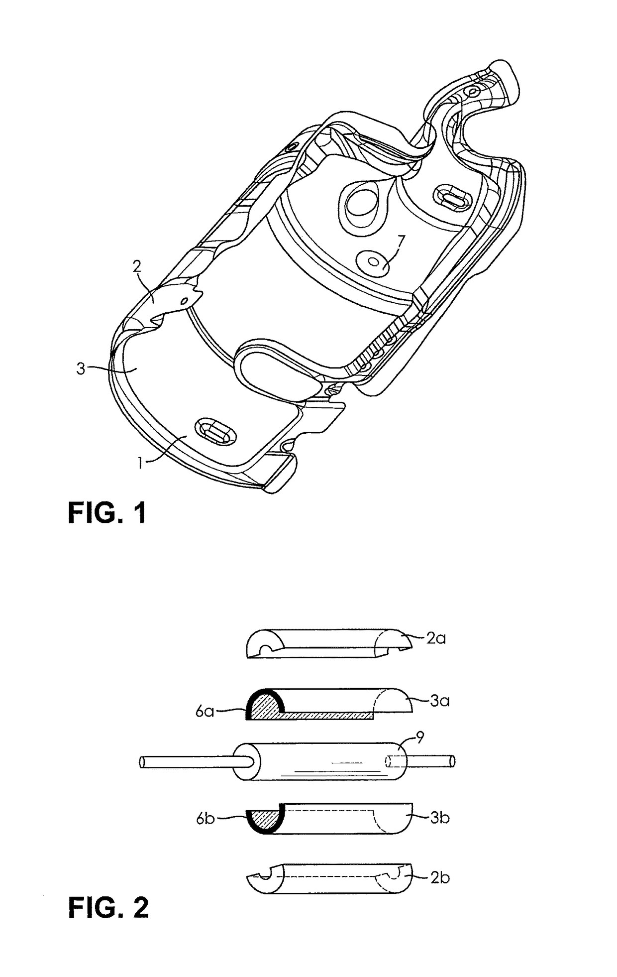
[0037]FIG. 1 is a plan view of the inside of a heat shield 1 with a sheet metal layer 2 and an insulating layer 3. The view in FIG. 1 is a plan view of the inside of the curved heat shield 1 on the exposed surface of the insulating layer 3. Openings 7 extend through the sheet metal layer 2 that covers the insulating layer 3 on the side away from the viewer and through the insulating layer 3, which are in the form of screw holes, for example.

[0038]FIG. 2 illustrates a system claimed by the invention with a heat shield claimed by the invention as illustrated in FIG. 1, in a schematic view in a combination view with an exhaust gas treatment system as the component 9, the hot areas of which are to be shielded. In this exploded view, the component 9 is surrounded and covered by two half-shells 3a and 3b of the insulating material as an insulating layer. Located above this insulating material are two half shells 2a and 2b of a sheet metal layer, that extend on their sides beyond the edges...


PUM

PropertyMeasurementUnit
outside diameteraaaaaaaaaa
inside diameteraaaaaaaaaa
thickness BSaaaaaaaaaa

Abstract

The invention relates to a heat shield for the shielding of hot areas of components, e.g. of internal combustion engines. The heat shield has an insulating layer (3) and a metallic sheet layer (2) that are located next to each other. The insulation contains or consists of hollow fibers (10) as insulating material. The hollow fibers (10), at least in sections or over their entire length, have a tubular, hollow, unfilled cross section.

Description

BACKGROUND OF THE INVENTION[0001]This invention relates to a heat shield, in particular of the type used to shield hot areas of components, e.g. of an internal combustion engine, and to a system with a heat shield of this type.[0002]Heat shields of this type often have a housing that is composed of two metallic sheet layers. These metallic sheet layers are connected with each other at least in some areas on their edges, wherein as an insulating layer an additional layer, namely an intermediate later, is frequently located between the layers of sheet metal. This intermediate layer contains or consists of thermal and / or acoustical insulating material.[0003]The prior art also includes heat shields in which one or more metallic sheet layers are located on only one side of an insulating layer. For assembly, the thermal and / or acoustical insulating layer is then laid directly on the component to be shielded. For this purpose, however, it is necessary to use sufficiently stable materials f...

Claims


Application Information

Patent Timeline
Patent Type & Authority Patents(United States)
IPC IPC(8): B32B15/00B32B15/14F02B77/11F16L59/22F16L59/147B60R13/08B32B5/02
CPCB32B15/14B32B5/024B60R13/0876F02B77/11F16L59/147F16L59/22B32B2605/08B32B2262/101B32B2262/108B32B2307/102B32B2307/304B32B2571/00B32B2250/02
Inventor SCHNEIDER, JUERGENSCHWEIGGART, FRANZRITZAL, AXEL
Owner REINZ DICHTUNGS
Why Eureka
Try Eureka