Differential voltage generator

a voltage generator and voltage field technology, applied in the direction of electric variable regulation, static storage, instruments, etc., can solve the problem that the switch-point voltage of single-ended sense devices may vary, leaving the initial target voltage unaffected

Active Publication Date: 2019-01-29
MARVELL ASIA PTE LTD
View PDF11 Cites 4 Cited by
  • Summary
  • Abstract
  • Description
  • Claims
  • Application Information

AI Technical Summary

Benefits of technology

[0026]Further, these methods remove the current generated by the first transistors (using corresponding ones of the second transistors), thereby causing an opposite current, and leaving the initial target voltage unaffected. Again, each first transistor has a corresponding second transistor that produces the same current as the first transistor to which it corresponds. More specifically, the current generated by the first transistors is removed from a resistor of the differential voltage generator by the opposing current generated by the second transistors. Thus, the second transistors generate an equal and opposite current through the resistor to prevent voltage changes caused by the first transistors from affecting the initial target voltage. These methods then output the altered target voltage from the first output, and output the initial target voltage from the second output.

Problems solved by technology

However, the switch-point voltage of single-ended sense devices may vary from device-to-device due to manufacturing process variations and / or environmental conditions.
Further, these methods remove the current generated by the first transistors (using corresponding ones of the second transistors), thereby causing an opposite current, and leaving the initial target voltage unaffected.

Method used


Image

  • Differential voltage generator
  • Differential voltage generator
  • Differential voltage generator

Examples


Embodiment Construction

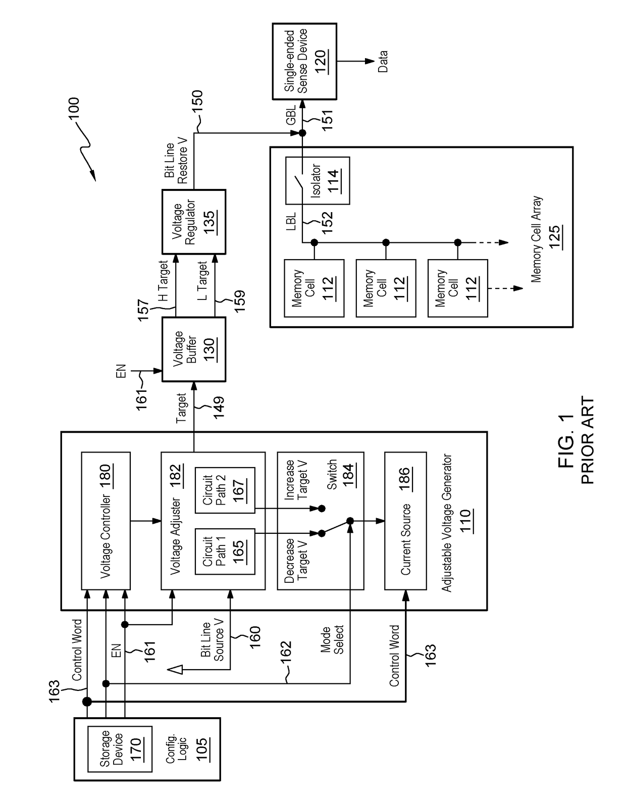
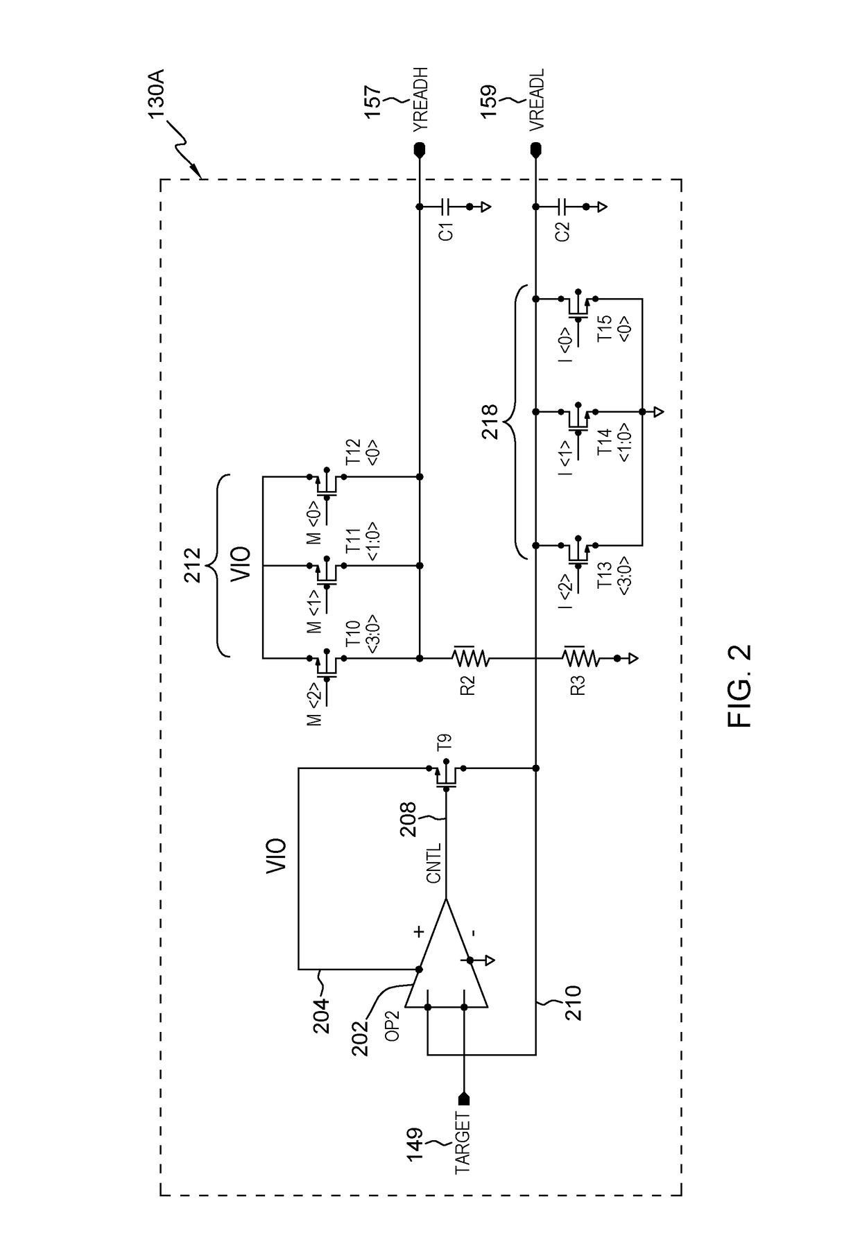
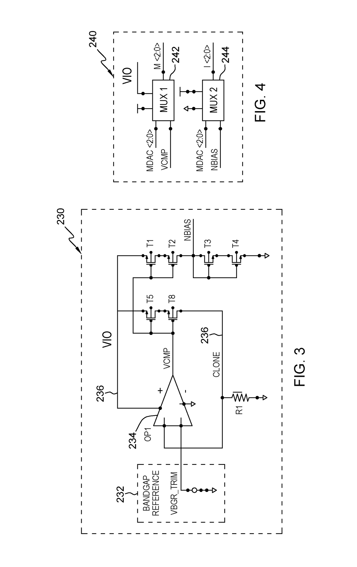
[0035]As mentioned above, conventional systems use differential voltage generators. Such systems that use a unity gain amplifier with an operational amplifier to buffer an input-voltage reference draw a fixed offset current through an offset resistor to ground; however, input-offset error is increased if the offset current is varied, because the gate voltage of the output transistor varies from its ideal operating point (near the voltage of the complementary operational amplifier node), and drain modulation reduces the gain and increases error. Additionally the operating range of such systems is limited by the cutoff of the output transistor, as offset-current is increased at higher differential voltage settings. The structures disclosed herein address this situation by applying equal and opposite currents to such an offset resistor. This allows the gate voltage of the output to not be disturbed by current passing thru the offset resistor, avoiding the offset current variation issue...


PUM


Abstract

Differential voltage generators receive an initial target voltage, and provide the initial target voltage to a first offset element and a second offset element. The first offset element includes first transistors, and the second offset element includes second transistors. Each of the first transistors is capable of changing the initial target voltage by a different incremental amount to change the initial target voltage to an altered target voltage. The second transistors are capable of removing a current generated by the first transistors, thereby causing an opposite current and leaving the initial target voltage unaffected on a second output. Each of the first transistors has a corresponding second transistor that produces the same current. A first output is capable of outputting the altered target voltage, and the second output is capable of outputting the initial target voltage.

Description

BACKGROUNDField of the Invention[0001]The present disclosure relates to charging circuits, and more specifically, to charging circuits that use differential voltage generators.Description of Related Art[0002]U.S. Pat. No. 9,000,837 to Fifield is partially incorporated herein and explains details of one type of dynamic random access memory (DRAM) device. More specifically, FIG. 1 (incorporated from U.S. Pat. No. 9,000,837) shows a block diagram of an exemplary DRAM 100 that may include configuration logic 105, an adjustable voltage generator 110, a single-ended sense device 120, a memory cell array 125, a voltage buffer 130, and a voltage regulator 135. The configuration logic 105 controls the adjustable voltage generator 110 to produce a target voltage 149. This voltage is used to generate a bit line restore voltage 150 that pre-charges a global bit line 151 (i.e., “GBL”) to a level that is the same as a switch-point voltage of the single-ended sense device 120. That is, the voltage...

Claims


Application Information

Patent Timeline
Patent Type & Authority Patents(United States)
IPC IPC(8): G11C5/14G05F1/595G05F1/10H03K17/16
CPCG11C5/14G05F1/10H03K17/164G05F1/595G11C5/147G11C11/4074G11C29/021G11C29/028G11C11/4094G11C11/4097G11C2207/002G11C2207/005
Inventor FIFIELD, JOHN A.HUNT-SCHROEDER, ERIC
Owner MARVELL ASIA PTE LTD
Why Eureka
Try Eureka