Indirect firing fastening tool, a propelling member and a fastener supporting such member for the tool, and a setting method for a fastener

a technology of propelling member and fastener, which is applied in the direction of threaded fasteners, manufacturing tools, mechanical apparatuses, etc., can solve the problems of increasing the longitudinal congestion of the tool, the bulky driving and propelling means formed by the piston, and the inability to meet the needs of the tool. achieve the effect of simple, efficient and economical

Active Publication Date: 2019-02-05
ILLINOIS TOOL WORKS INC
View PDF16 Cites 1 Cited by
  • Summary
  • Abstract
  • Description
  • Claims
  • Application Information

AI Technical Summary

Benefits of technology

[0009]In the present application, a “direct cooperation” between two parts means a cooperation with no intermediate part, and in particular with no intermediate part not being translationally connected with the fastener. In the present case, a rotation of the driving means directly leads to a movement, in particular a translational one, of the fastener. The contact or the contact biasing between the driving means and the fastener or the propelling member thereof can be sufficient so that the fastener is driven due to the rotation of such means.
[0011]The fastener can comprise a portion embedded into the propelling member which can form an axial extension of the fastener so that the member enables to continue the propulsion of the fastener up to the full driving thereof into the support. Such member further allows the propulsion conditions for the fastener to be improved by increasing the energy transmission from the driving means.
[0015]Preferably, the space between the flywheels has a transversal dimension being lower than at least part of the fastener or the member supported by the latter, so that the fastener or the member thereof is press fitted between the flywheels upon firing and avoids any sliding between the fastener and the flywheels or between the propelling member and the flywheels. The materials of the flywheels, the fastener and / or the propelling member can be selected so as to allow for such press fitting while guaranteeing an optimum lifetime for the tool. The propelling member is for instance made of a less hard material than the fastener one and adapted to be deformed upon firing so as to maximize the energy transmission from the flywheels.
[0020]The driving motors for the inertial flywheels can be electrical motors, thereby simplifying the concept of the tool and allowing in particular handheld fastening tools to be manufactured with rechargeable electrical battery.
[0023]Advantageously, at least one of the flywheels is biased towards the other flywheel. In the above mentioned case where the fastener is engaged in the inter flywheel space, the biasing of one flywheel in the direction of the other flywheel allows to press more the fastener or the propelling member between the flywheels and thus to improve the transmission of energy between the flywheels and the fastener or the member while avoiding any sliding risk. A first flywheel can be biased towards the second flywheel by moving the first flywheel in a direction being substantially perpendicular to the rotation axes of the flywheels. In this case, the second flywheel is mounted stationary in the tool, whereas the first flywheel is biased towards the second flywheel, for example by at least one compression spring mounted between the first flywheel and a stationary part of the tool. Alternatively, the two flywheels can be biased towards each other. Each flywheel can then be biased towards the other flywheel through the compression spring mounted between the flywheel and a stationary part of the tool.
[0027]The propelling member can include at least one weakening longitudinal slot configured to make its dissociation from the fastener easier upon the setting of the latter. Upon firing, the propelling member contacts the support and is deformed so as to be dissociated from the fastener. The longitudinal slot of the member may be designed to cause the member along such slot to be torn and the member parts located on either side of such slot to be torn apart.

Problems solved by technology

The fastener driving and propelling means being here formed by the piston are bulky in particular along the fastener propelling axis.
Such congestion problem also exist in the case of a tool, the driving and propelling means of which comprise a driver blade, because of the stroke to be provided for such driver blade and means for guiding the latter.
Moreover, the return means of the driving means into their initial position further increase the tool longitudinal congestion, as well as the complexity of the latter.

Method used


Image

  • Indirect firing fastening tool, a propelling member and a fastener supporting such member for the tool, and a setting method for a fastener
  • Indirect firing fastening tool, a propelling member and a fastener supporting such member for the tool, and a setting method for a fastener
  • Indirect firing fastening tool, a propelling member and a fastener supporting such member for the tool, and a setting method for a fastener

Examples


Embodiment Construction

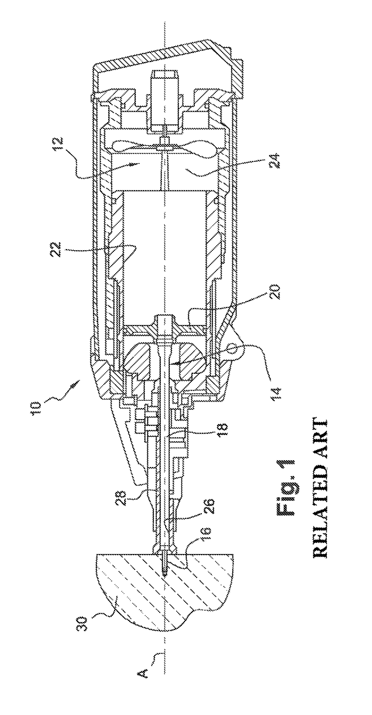
[0038]It is first referred to FIG. 1 representing an indirect firing fastener tool 10 according to the state of the art, such tool being here a nailing machine with an internal combustion engine 12. The tool 10 includes one piston 14 for driving a nail 16, such piston comprising a rod 18 connected on one end to a head 20 which can be moved into translation within a cylindrical housing 22 of the tool under the action of the fuel firing within the combustion chamber 254 of the tool.

[0039]Upon a firing, the rod 18 of the piston 14 is moved into translation in the bore 26 of a pin guide 28 and will strike the nail 16 to propel it into a support 30.

[0040]As above explained, the piston 14 forming the driving and propelling means for the nail 16 has a longitudinal dimension (along the axis A) being quite important and thus creates an important longitudinal congestion.

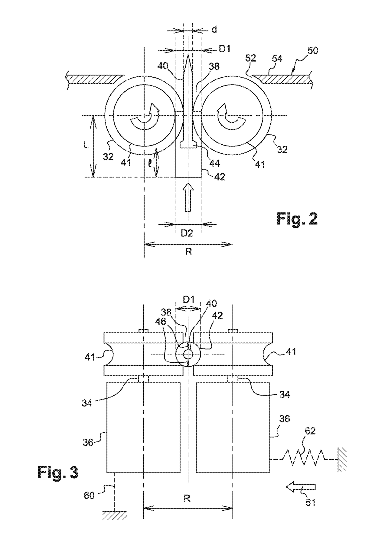
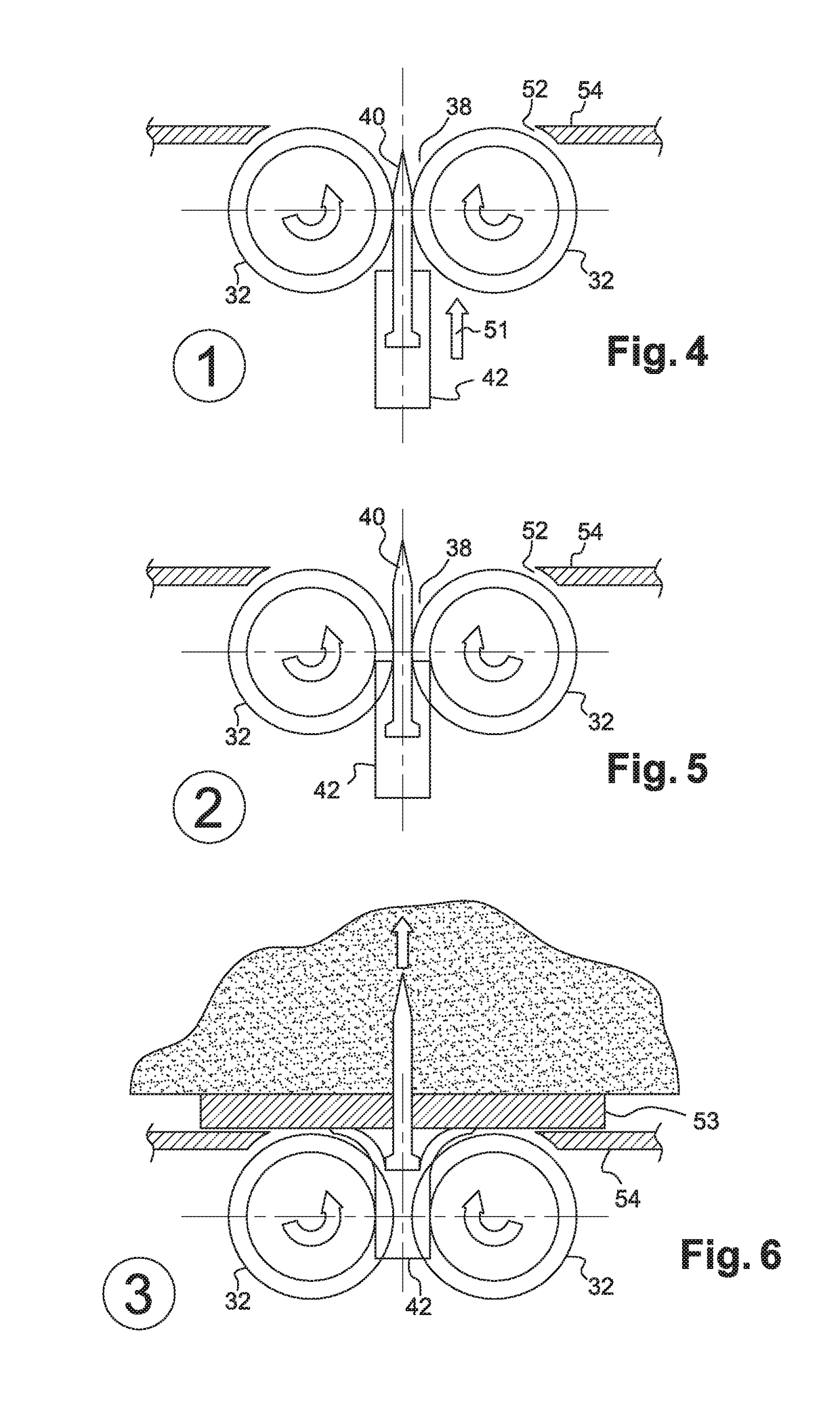
[0041]The present invention allows such problem to be remedied thanks to new driving and propelling means which are mobile i...


PUM

PropertyMeasurementUnit
speedaaaaaaaaaa
transversal dimensionaaaaaaaaaa
diameteraaaaaaaaaa

Abstract

An indirect firing fastening tool, comprising driving and propelling means for a fastener to be set into a support, such driving means being rotationally mobile and configured to directly cooperate with the fastener or with a propelling member supported by the latter, so that a rotation of the driving means directly causes the translational driving and the propulsion of the fastener.

Description

RELATED APPLICATIONS[0001]The present application is a National Phase of International Application Number PCT / US2014 / 035103 filed Apr. 23, 2014 and claims priority to French Application Number 1355472 filed Jun. 13, 2013.TECHNICAL FIELD[0002]The present invention relates to an indirect firing fastening tool, a fastener propelling member, an assembly comprising a fastener and a propelling member, as well as a setting method for a fastener into a support.STATE OF THE ART[0003]A fastening or setting tool enables to propel a fastener, such as a nail, a pin, a staple, etc., into a support. The use of the direct firing tools, where the propulsion energy is directly transmitted to the fastener, is prohibited. In an indirect firing fastening tool, such energy is generally transmitted to the fastener through a driver blade or a piston to store energy, transmit it to the fastener to be propelled, and store the residual energy once the fastener is propelled. The propulsion energy can come from...

Claims


Application Information

Patent Timeline
Patent Type & Authority Patents(United States)
IPC IPC(8): B25C1/06
CPCB25C1/06B21C51/005B23P19/064F16B9/07F16B37/068B25B23/045F16B15/02F16B15/00B25D11/06
Inventor RICORDI, CHRISTIAN
Owner ILLINOIS TOOL WORKS INC
Why Eureka
Try Eureka