
LED lighting apparatus having natural convection-type heat dissipation structure

a technology of heat dissipation structure and led lighting, which is applied in the direction of lighting and heating apparatus, semiconductor devices for light sources, and lighting support devices. it can solve the problems of deteriorating the performance of led devices, short lifespan of fans, and large amount of led devices, so as to reduce manufacturing costs, reduce maintenance costs, and reduce the effect of cost of components

Active Publication Date: 2019-02-05
SAMJIN LND
View PDF20 Cites 5 Cited by
  • Summary
  • Abstract
  • Description
  • Claims
  • Application Information

AI Technical Summary

Benefits of technology

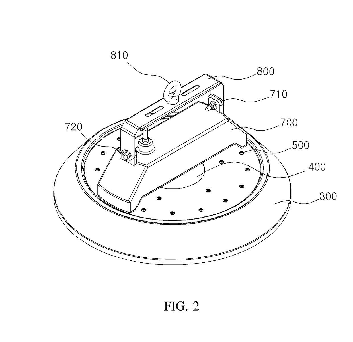
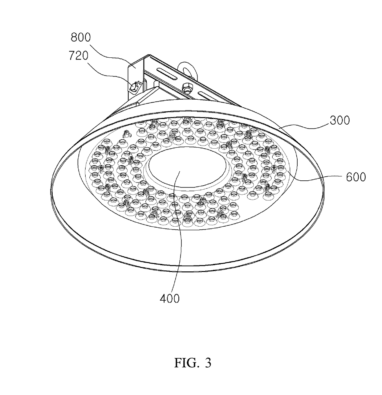
[0016]Accordingly, the present invention has been made keeping in mind the above problems occurring in the prior art, and an object of the present invention is to provide an LED lighting apparatus having a natural convection-type heat dissipation structure, the apparatus including: a printed circuit board (PCB) on which a light emitting diode (LED) device is mounted; and a heat sink coupled to a back surface of the PCB, absorbing heat generated by the LED device, and having a convection hole at a center portion thereof, the convection hole causing natural convection such that hot air surrounding the LED device rises and the surrounding cooler air moves to around the LED device to replace the hot air, thereby dramatically increasing heat dissipation efficiency.
[0017]Another object of the present invention is to provide an LED lighting apparatus having a natural convection-type heat dissipation structure that can reduce manufacturing cost, saves maintenance cost, has a simple and lightweight structure, and enables easy installation and use.

Problems solved by technology

At this point, the LED device also generates a large amount of heat.
The heat generated by an LED device during its operation deteriorates performance of the LED device.
However, it suffers problems such as frequent malfunctioning and a short lifespan of a fan attributable to friction and wear, and it requires additional accessories such as an electric motor (or membrane) for driving the fan, which increases cost.
However, the above-described passive cooling methods are problematic in that manufacturing of a heat sink equipped with a plurality of heat dissipation fins increases the cost of a lighting apparatus because the cost includes cost for component parts, cost for molds, and cost for assembling.
Furthermore, due to a heat sink attached to a lighting apparatus, the lighting apparatus inevitably becomes complicated, larger, and heavier.

Method used


Image

  • LED lighting apparatus having natural convection-type heat dissipation structure
  • LED lighting apparatus having natural convection-type heat dissipation structure
  • LED lighting apparatus having natural convection-type heat dissipation structure

Examples


examples

[0082]Hereinafter, the results of temperature comparison between an LED lighting apparatus of a comparative example and an LED lighting apparatus of the preferred embodiment will be described. For this experiment, an LED lighting apparatus (comparative example) equipped with a heat sink having no convection hole and an LED lighting apparatus (preferred embodiment) equipped with a heat sink provided with a convection hole are manufactured, and their temperatures are measured.

embodiment

Preferred Embodiment

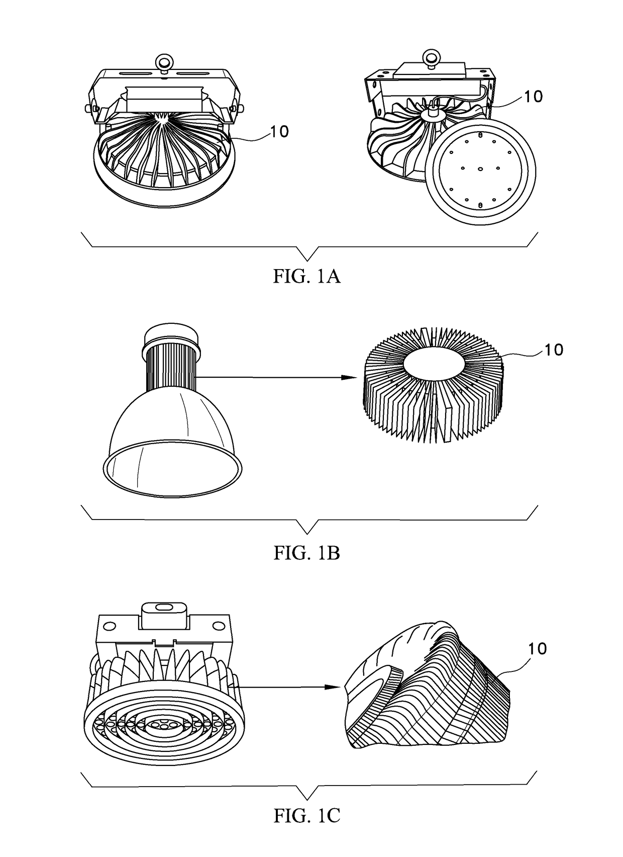
[0084]A truncated cone-shaped heat sink for absorbing heat is coupled to a back surface of a PCB to which a plurality of LED devices is mounted, in which center portions of the PCB and the heat sink are provided with a convection hole.

[0085](Experiment)

[0086]In the comparative example and the preferred embodiment, the LED devices that are mounted are the same kind. In addition, the LED lighting apparatuses according to the comparative example and the preferred embodiment were turned on for a predetermined period of time under the same conditions, and temperatures were measured at the upper surfaces of the LED lighting apparatuses. The measured temperatures are shown in Table 1.

[0087]

TABLE 1TemperatureTemperatureTemperatureTemperatureof LEDof LEDof LEDat upper endItemsdevice 1device 2device 3of heat sinkComparative51.5□52.2□50.6.□51.4□example (LEDlightingapparatushaving heatsink with noconvectionhole)Embodiment44.1□44.7□43.1□43.7□(LED lightingapparatushaving heats...


PUM


Abstract

Disclosed is an LED lighting apparatus having a natural convection-type heat dissipation structure. The LED lighting apparatus includes a heat sink coupled to a back surface of a printed circuit board (PCB) to which a plurality of light emitting diode (LED) devices is mounted and, and functioning to absorb heat generated by the LED devices, in which center portions of the heat sink and the PCB are provided with openings serving as a convection hole that induces natural convection such that hot air under the heat sink rises along with rising hot air attributed to heat radiated from an upper surface of the heat sink and surrounding cooler air is supplied to the upper surface the heat sink and to around the LED devices. Due to the convection hole, the LED lighting apparatus provides a heat dissipation effect as high as that of an active cooling system.

Description

CROSS REFERENCE TO RELATED APPLICATION[0001]The present application claims priority to Korean Patent Application No. 10-2017-0009996, filed Jan. 20, 2017, the entire contents of which is incorporated herein for all purposes by this reference.BACKGROUND OF THE INVENTIONField of the Invention[0002]The present invention generally relates to an LED lighting apparatus having a natural convection-type heat dissipation structure. More particularly, the present invention relates to an LED lighting apparatus having a natural convection-type heat dissipation structure capable of increasing heat dissipation efficiency by causing natural convection that is a mechanism in which air surrounding a light emitting diode (LED) device receives heat, becomes less dense, and rises, and the surrounding cooler air then moves to replace it.Description of the Related Art[0003]Generally, a light emitting diode (LED) device that constitutes an LED lighting apparatus emits light when it is supplied with electr...

Claims


Application Information

Patent Timeline
Patent Type & Authority Patents(United States)
IPC IPC(8): F21V29/75F21V3/00F21V23/02F21V29/83F21V21/14F21V17/10F21Y115/10
CPCF21V29/75F21V3/00F21V17/10F21V23/02F21V29/83F21V21/14F21Y2115/10F21V21/30F21V23/023F21V29/763F21Y2105/18
Inventor SOHN, CHOONG-YONGSONG, JUN-HOKIM, JIN-MO
Owner SAMJIN LND
Learn More