Liquid dispensing nozzle and device comprising a cap

a liquid dispensing nozzle and liquid technology, applied in the field of liquid dispensing nozzles, can solve the problems of not being able to unscrew and not being able to turn, and achieve the effects of improving air circulation, reducing noise, and improving evaporation of residual liquid products

Active Publication Date: 2019-02-12
NEMERA LA VERPILLIERE SAS
View PDF15 Cites 23 Cited by
  • Summary
  • Abstract
  • Description
  • Claims
  • Application Information

AI Technical Summary

Benefits of technology

[0005]Thus there is proposed a nozzle in which the exterior envelope and the interior envelope are advantageously able to assume a configuration allowing air to pass between them, whilst offering improved safety. In fact, a sufficiently high bearing force on the exterior envelope is required to unscrew the cap. Unscrewing remains simple and intuitive for an adult whereas a child, who is not capable of turning while pressing or of pressing sufficiently firmly on the exterior envelope, will find itself only in the safety configuration of the cap and will not be able to unscrew it. Said bearing force exerted on the cap is preferably, but not exclusively, an axial bearing force. Moreover, when the cap is in the unscrewing configuration, the exterior envelope is driven in rotation in the first direction, which is preferably the anticlockwise direction, corresponding to the classic unscrewing direction. Thanks to the bearing force applied to the exterior envelope, the interior envelope is also driven to turn in the same direction, which allows unscrewing of the cap. Clearly the means for blocking the evaporation path, when in the blocking position, enable a nozzle to be provided that is fluid-tight prior to its first use. It is therefore possible to limit evaporation of the liquid contained in the nozzle during storage of the nozzle and contamination of the nozzle by dust or microorganisms during storage. After the first opening of the cap, that is to say when the cap is in a configuration other than the storage configuration, the blocking means pass to the position opening the evaporation path. Because of this, air is advantageously able to pass between the two envelopes and enable evaporation of the liquid via that evaporation path. This makes it possible to prevent liquid stagnating at the dispensing opening of the nozzle, and therefore the growth of bacteria. It will be noted that the blocking means remain in the opening position and the evaporation path remains operational in the safety configuration, and preferably also in the unscrewing configuration. In other words, the evaporation path is blocked or opened by the blocking means, which, once in the opening position, remain in that position permanently, without regard to the movement or the position of the exterior and interior envelopes.
[0017]Clearly in the situation where the interior envelope is driven by abutment, the unscrewing projection comes into contact with the unscrewing surface only in the unscrewing configuration. Driving by abutting has the advantage of improved handling of the nozzle because this requires less force to open the cap.

Problems solved by technology

Unscrewing remains simple and intuitive for an adult whereas a child, who is not capable of turning while pressing or of pressing sufficiently firmly on the exterior envelope, will find itself only in the safety configuration of the cap and will not be able to unscrew it.

Method used


Image

  • Liquid dispensing nozzle and device comprising a cap
  • Liquid dispensing nozzle and device comprising a cap
  • Liquid dispensing nozzle and device comprising a cap

Examples


first embodiment

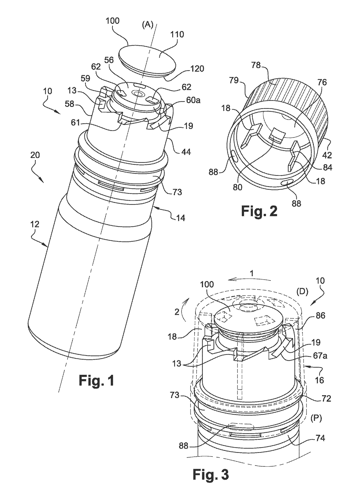
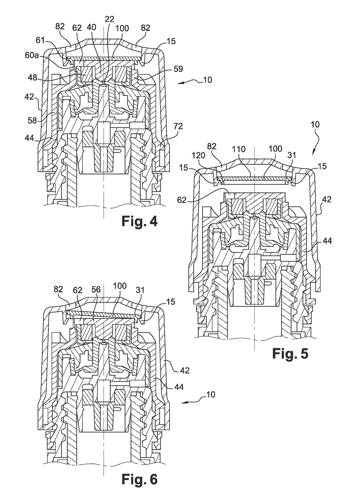
[0051]FIGS. 1 to 6 illustrate the nozzle 10 in which the interior envelope 44 comprises a ceiling 56, a first skirt 58 and a second skirt 59, both of substantially cylindrical shape, interconnected by a plate 61 (see FIG. 1). The ceiling 56 is delimited in this example by a cylindrical surface 60a connecting it to the second skirt 59 and comprises air passage orifices 62, three of them in this example. The cylindrical surface 60a defines a sealing surface. The interior envelope 44 further comprises a peripheral circular groove 73 arranged at the proximal end (P) of the interior envelope 44. The interior envelope 44 further comprises a plurality of guide slopes 67a (see FIG. 3) spaced from one another and extending from the first skirt 58 in the axial direction (A), each guide slope 67a having a sliding surface 19 and a screwing abutment 13. The interior envelope 44 further comprises a frangible ring 74 at the proximal end (P) of the cap 16, as can be seen in FIG. 3.

[0052]As shown in...

second embodiment

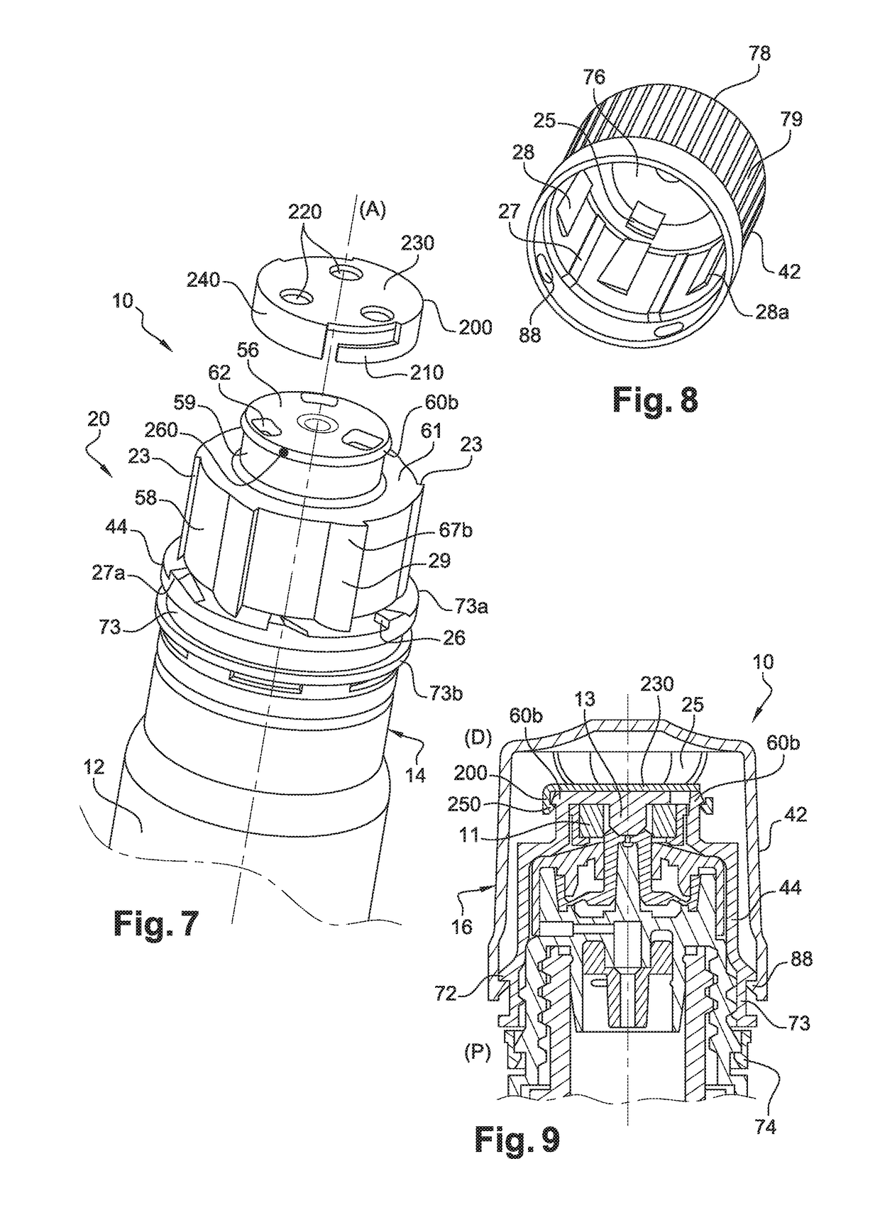
[0064]FIGS. 7 to 11 illustrate the nozzle 10 in which the interior envelope 44 comprises a ceiling 56, a first skirt 58 and a second skirt 59 both of substantially cylindrical shape interconnected by a plate 61. The ceiling 56 comprises air passage orifices 62, three of them in this example. The second skirt 59 comprises at its end a flange 60b having a substantially frustoconical peripheral surface in which are arranged two stopping points 260 on respective opposite sides of the axis of the nozzle 10. In this example the ceiling 56 defines a sealing surface. The interior envelope 44 further comprises a plurality of guide slopes 67b spaced from one another and extending from the first skirt 58 in a transverse direction relative to the axial direction (A), each guide slope 67b including a sliding surface 29 and a screwing abutment 23. The interior envelope 44 further comprises a frangible ring 74 at the proximal end (P) of the cap 16, as can be seen in FIG. 9.

[0065]As in the first em...

third embodiment

[0081]FIGS. 12 to 17 illustrate the nozzle 10 in which the interior envelope 44 comprises a ceiling 56, a first skirt 58 and a second skirt 59 both of cylindrical shape interconnected by a plate 61. As can seen in FIG. 12, the ceiling 56 comprises air passage orifices 62, three of them in this example. The second skirt 59 comprises return means in the form of a deformable wall 60c (see FIG. 15) extending from the periphery of the ceiling 56 and comprises an interior rim at its distal end (D). In this example the rim defines a sealing surface. The interior envelope 44 further comprises a plurality of guide slopes 67c spaced from one another and extending from the first skirt 58 in a transverse direction relative to the axial direction (A), each guide slope 67c including a sliding surface 39 and a screwing abutment 33 (see FIG. 12). The interior envelope 44 further comprises a frangible ring 74 at the proximal end (P) of the cap 16, as can be seen in FIG. 14.

[0082]The interior envelop...


PUM


Abstract

A liquid dispensing nozzle having an opening, a removable cap, a residual liquid evaporation path between the opening and the exterior of the nozzle, an element for blocking the evaporation path, mobile in the cap between a blocking position and a position opening the evaporation path, the cap including an exterior envelope and an interior envelope that are coaxial, and mobile relative to one another in an axial direction between: a storage configuration; a configuration for unscrewing the cap when a bearing force exerted on the cap has an intensity greater than a predetermined threshold; a safety configuration if a bearing force exerted on the cap has an intensity lower than the predetermined threshold or if no bearing force is exerted on the cap, the blocking element being configured to be driven by the movement of the exterior envelope to pass from the blocking position to the opening position.

Description

FIELD OF THE INVENTION[0001]The present invention concerns the technical field of dispensing liquids. It concerns in particular, but not exclusively, the field of dispensing liquids in the form of droplets or in the form of a spray, such as ophthalmic, nasal, buccal or auricular liquid.BACKGROUND OF THE INVENTION[0002]There has already been proposed in the document WO2013 / 140069 a liquid dispensing device comprising a reservoir and a dispensing nozzle provided with a removable cap. The cap described in the above document comprises two envelopes mobile relative to one another in order to be able to create an air passage allowing evaporation of residual liquid located at the level of the dispensing orifice. It is found that this cap is opened simply by unscrewing it, with the result that the liquid product contained in the reservoir becomes easily accessible via the dispensing nozzle. This presents a hazard for a young child who may, by manipulating the device, manage to open the cap ...

Claims


Application Information

Patent Timeline
Patent Type & Authority Patents(United States)
IPC IPC(8): B65D47/00B65D51/24
CPCB65D51/24B65D47/00B65D47/18B65D50/041B65D51/228B65D2251/0015B65D2251/009
Inventor PAINCHAUD, GAETAN
Owner NEMERA LA VERPILLIERE SAS
Why Eureka
Try Eureka