
Centrifugal compressor apparatus and method for preventing surge therein

a centrifugal compressor and compressor technology, applied in mechanical equipment, machines/engines, liquid fuel engines, etc., can solve the problems of compressor damage, compressor failure to stably operate, compressor life shortened, etc., to and reduce the risk of compressor failur

Active Publication Date: 2019-02-12
IHI ROTATING MACHINERY ENG CO LTD
View PDF46 Cites 1 Cited by
  • Summary
  • Abstract
  • Description
  • Claims
  • Application Information

AI Technical Summary

Benefits of technology

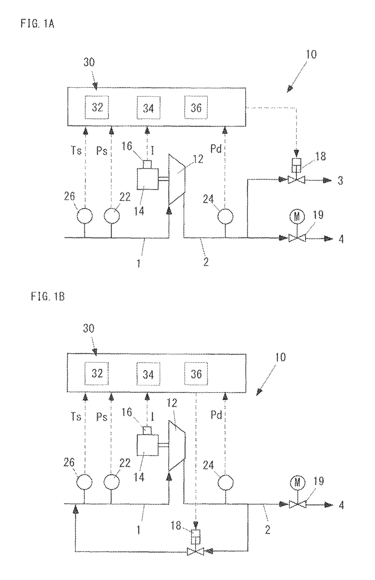
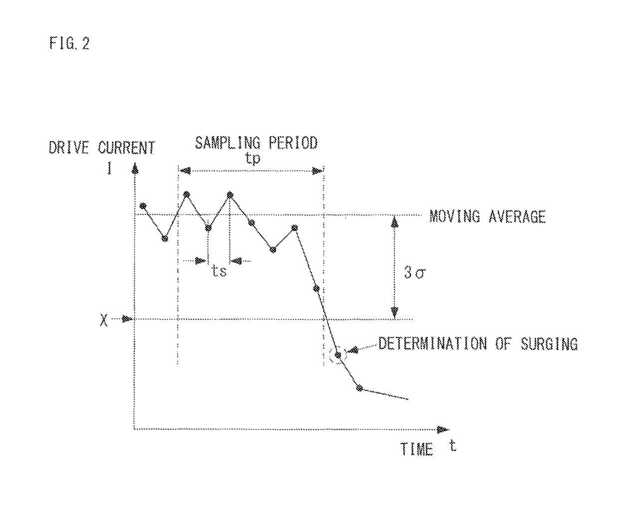
The present invention provides a device and method for preventing surging in a centrifugal compressor. Surging occurs when the compressor is operating at a high speed and there is a sudden increase in the power demand. This can cause damage or malfunction. The invention uses a statistical technique to estimate the fluctuation in the drive current and calculates a standard deviation to determine if surging has occurred. The device can also update the current threshold in real-time and automatically update a surge line to follow changes in the operating environment. This allows for reliable detection and prevention of surging without being affected by fluctuations in the drive current. The invention can significantly widen the capacity control range of the centrifugal compressor and provide stable operation even at high speeds.

Problems solved by technology

When the centrifugal compressor is in a surging state, the compressor cannot stably operate and the life of the compressor is shortened.
At worst, there is also a possibility that the compressor is damaged.

Method used


Image

  • Centrifugal compressor apparatus and method for preventing surge therein
  • Centrifugal compressor apparatus and method for preventing surge therein
  • Centrifugal compressor apparatus and method for preventing surge therein

Examples


embodied example 1

1. Non-Dimensionalization of Surge Line 5

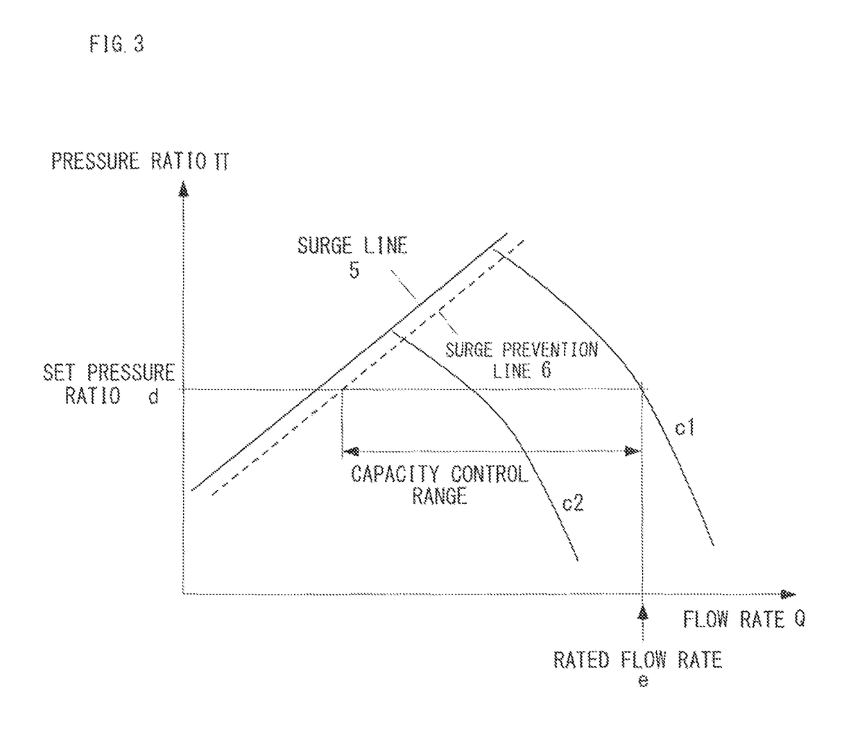
[0133]If the fluctuation in temperature and atmospheric pressure caused by the change of season is not corrected for a performance chart between the current I and the discharge pressure Pd, the surge line 5 is changed depending on a season or an operating place. It is possible to standardize the change of performance due to these conditions by converting the performance chart between the current I and the discharge pressure Pd into a performance chart (see FIG. 3) between the flow rate Q and the pressure ratio Π. The pressure ratio Π can be obtained from the suction pressure Ps and the discharge pressure Pd, and the flow rate can be obtained from the correction formula (1) of Formula 1.

[0134]⁢[Formula⁢⁢1]Q⁡(I,Ps,Pd,Ts)≈α⁢⁢ILn⁡(PdPs)·Ts+273.15273.15=α⁢⁢ILn⁢⁢Π·Ts+273.15273.15(1)

[0135]In this regard, α is a constant, Ps and Pd are absolute pressure, and Ts is suction temperature. When the centrifugal compressor 12 is an air compressor, “Ps≈1” an...


PUM


Abstract

There is provided a centrifugal compressor apparatus including a centrifugal compressor that centrifugally compresses a gas, an electric motor that rotatably drives the centrifugal compressor, a current detector that detects a drive current I of the electric motor, and an exhaust valve that discharges a compressed gas to a lower pressure section. The centrifugal compressor apparatus (A) detects the drive current I at a sampling cycle ts, (B) updates, as a current threshold, in real time, a value “(moving average)−n×(standard deviation)” for which a plurality of drive currents measured in a sampling period tp serves as a population, where n is a positive number in the range of 3 to 4 and, (C) determines that surging has occurred when the exhaust valve is closed and the drive current I is below the current threshold X, and (D) further opens the exhaust valve to discharge the compressed gas when determining that surging has occurred.

Description

[0001]This is a Continuation Application in the United States of International Patent Application No. PCT / JP2012 / 075513 filed Oct. 2, 2012, which claims priority on Japanese Patent Application No. 2011-218955 filed Oct. 3, 2011. The entire disclosures of the above patent applications are hereby incorporated by reference.TECHNICAL FIELD[0002]The present invention relates to a centrifugal compressor apparatus using a centrifugal compressor and a method of preventing surging therein.BACKGROUND ART[0003]Surging that accompanies extreme pressure fluctuation and noise occurs in a low flow rate region in a centrifugal compressor used in a turbo compressor or a turbo refrigerator. When the centrifugal compressor is in a surging state, the compressor cannot stably operate and the life of the compressor is shortened. At worst, there is also a possibility that the compressor is damaged.[0004]In view of it, various means for preventing the occurrence of surging were proposed in the past (for ex...

Claims


Application Information

Patent Timeline
Patent Type & Authority Patents(United States)
IPC IPC(8): F04D27/02F04D27/00F04D25/06F04D17/10
CPCF04D27/0223F04D25/06F04D27/001F05D2270/335F04D17/10F04D27/0207F04D1/02F04D25/08F04D27/02F04D29/66
Inventor KOKI, TSUNEONISHIYAMA, NAOKIECHIZEN, YUJIOYABU, TAKASHISEKI, TOMONORIMORIGUCHI, MASASHI
Owner IHI ROTATING MACHINERY ENG CO LTD
Learn More