Hydrogen sensor and sensor circuit

a sensor circuit and hydrogen sensor technology, applied in the field of hydrogen sensors, can solve the problems of difficult to widely apply hydrogen gas in our real life, high current signal of conventional hydrogen sensors, and high risk of explosion of hydrogen gas, and achieve the effect of reducing the concentration of hydrogen

Active Publication Date: 2019-02-12
IND ACADEMIC COOP FOUND YONSEI UNIV
View PDF10 Cites 0 Cited by
  • Summary
  • Abstract
  • Description
  • Claims
  • Application Information

AI Technical Summary

Benefits of technology

[0008]Accordingly, the present invention has been made keeping in mind the above problems occurring in the related art, and an object of the present invention is to provide a hydrogen sensor capable of easily and rapidly detecting a low concentration of hydrogen.
[0019]According to the present invention, the hydrogen-sensing unit is connected to the transistor or resistor, so it is possible to detect a lower concentration of hydrogen.

Problems solved by technology

However, since hydrogen gas runs the risk of explosion if exposed to air by 4% or more, it is difficult to widely apply hydrogen gas in our real life if safety-in-use is not secured.
A conventional hydrogen sensor, however, has a problem of a low current signal.
However, in a conventional hydrogen sensor, a current signal induced from a low hydrogen concentration is so low that, even when converted into a voltage signal, it is difficult to check whether the converted voltage signal indicates an ON or OFF signal.

Method used


Image

  • Hydrogen sensor and sensor circuit
  • Hydrogen sensor and sensor circuit
  • Hydrogen sensor and sensor circuit

Examples


Embodiment Construction

[0028]Hereinbelow, preferred embodiments of the present invention will be described in detail with reference to the accompanying drawings. In the description, well-known technologies in the art will be omitted. Although such a description is omitted, persons skilled in the art, however, will appreciate characteristic features of the present invention when reading and understanding the following description.

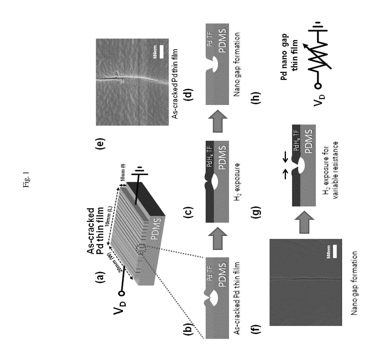
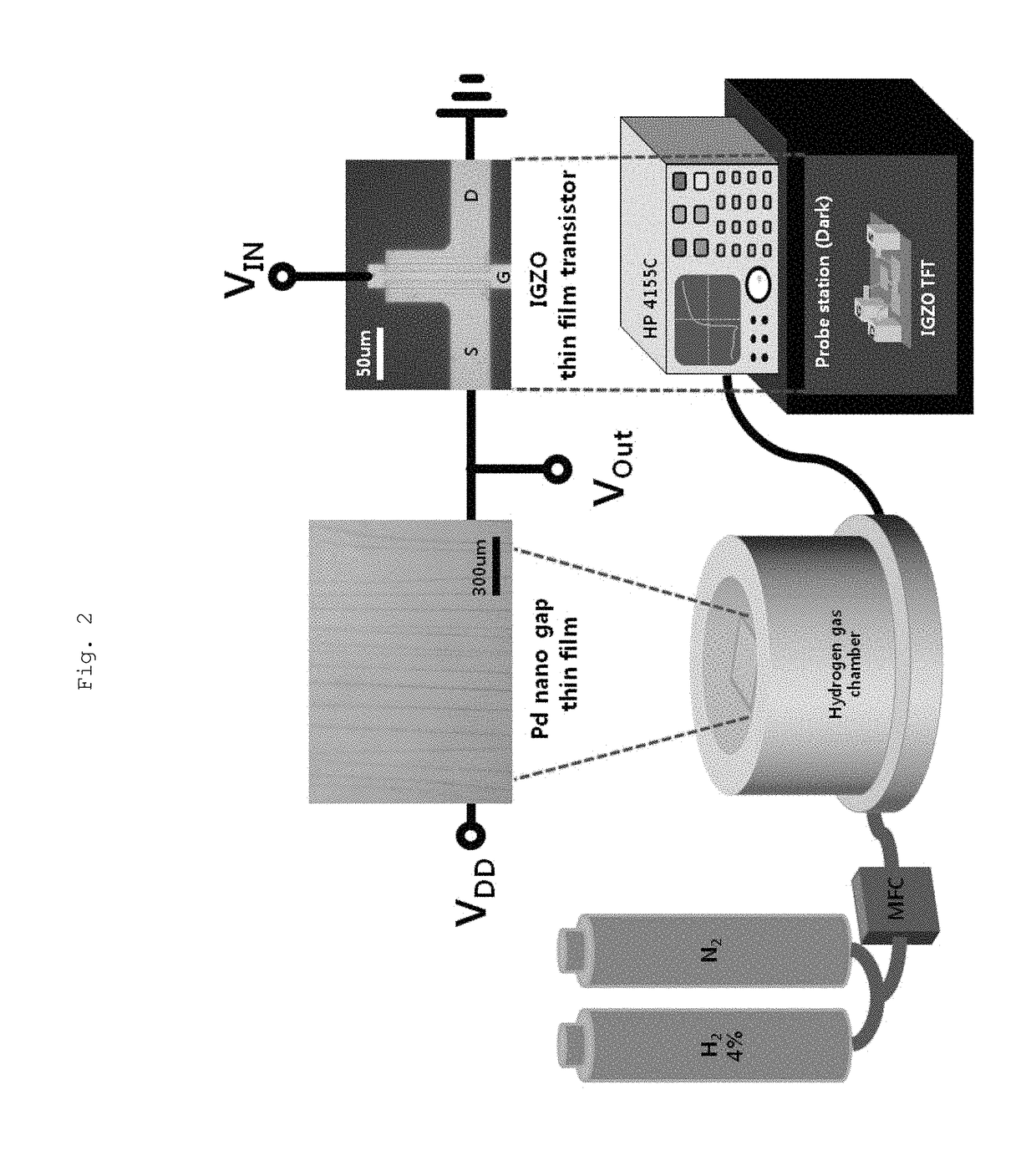
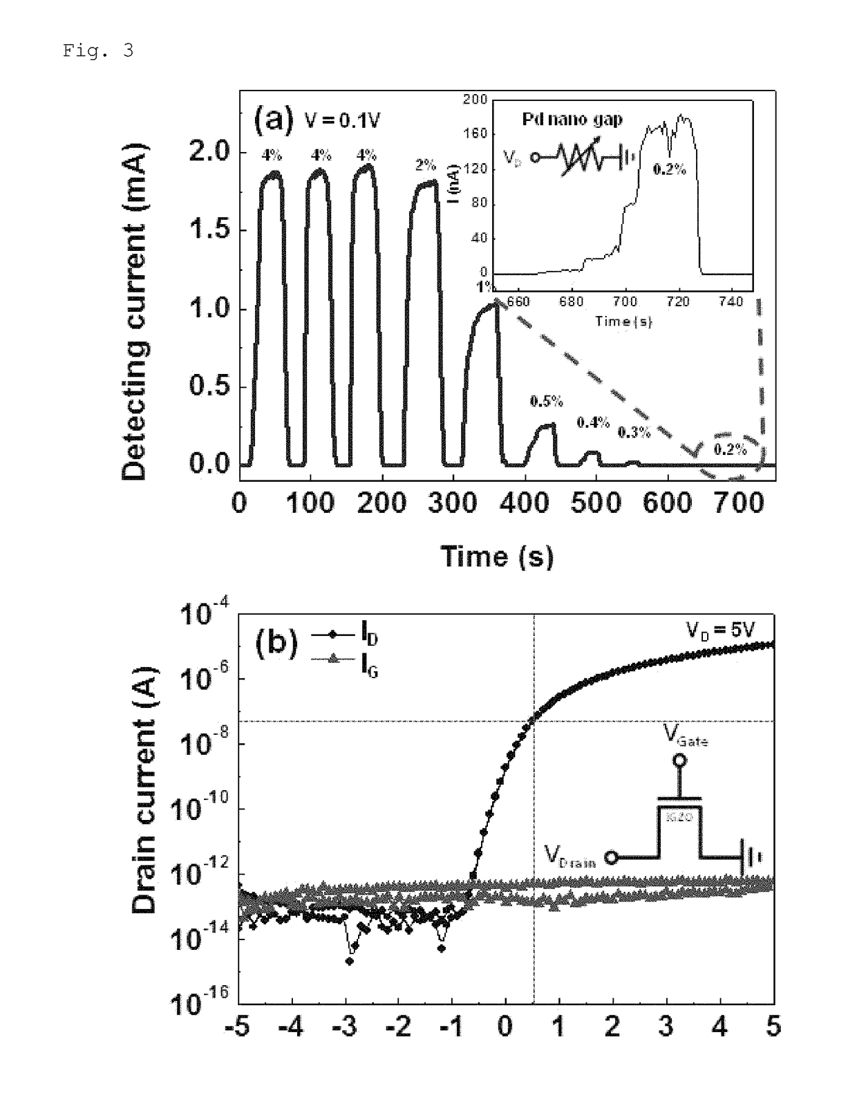
[0029]As described in detail below, the present invention proposes a hydrogen sensor system in which the hydrogen sensing capability of a nanogap-based Pd sensor is improved by connecting the Pd sensor to an electrically stable amorphous InGaZnO thin-film transistor (a-IGZO TFT) in two different ways: Pd connection to the TFT source and to the gate. In one embodiment, the IGZO TFT is chosen, since it is stable enough to bear the gate bias stress during hydrogen detection; it would eventually be integrated with the present Pd sensor. As a result of the Pd connection to the TFT sour...


PUM

PropertyMeasurementUnit
width-to-lengthaaaaaaaaaa
thickaaaaaaaaaa
volumeaaaaaaaaaa

Abstract

A hydrogen sensor includes a hydrogen-sensing unit and a transistor connected to the hydrogen-sensing unit. The hydrogen-sensing unit includes a substrate made of an elastic material, a thin film made of transition metal or alloy thereof, disposed on the surface of the substrate and having a plurality of nanogaps formed therein, and an electrode formed on the thin film. The hydrogen-sensing unit is connected with a source (or drain) or a gate of the transistor via a connector.

Description

BACKGROUND OF THE INVENTION[0001]Field of the Invention[0002]The present invention relates, in general, to a hydrogen sensor.[0003]Description of the Related Art[0004]Generally, hydrogen energy has been actively studied since it is reusable and has an advantage in that it does not induce environmental pollution.[0005]However, since hydrogen gas runs the risk of explosion if exposed to air by 4% or more, it is difficult to widely apply hydrogen gas in our real life if safety-in-use is not secured. Therefore, along with the studies on utilization of hydrogen energy, a hydrogen gas-detection sensor (simply referred hereinafter to as a ‘hydrogen sensor’) has been developed in order to, in practical use, detect leakage of the hydrogen gas in early stages.[0006]In the meantime, as hydrogen energy is availably commercialized, it is expected to be first applied to the automobile markets. Considering that researches are currently carried out on loading compressed hydrogen gas on an automobil...

Claims


Application Information

Patent Timeline
Patent Type & Authority Patents(United States)
IPC IPC(8): G01N33/00H01L29/786G01K7/01
CPCG01N33/005G01K7/015H01L29/78693H01L29/786G01N33/0036
Inventor LEE, WOOYOUNGIM, SEONGILLEE, YOUNGTACKJUNG, HWAEBONG
Owner IND ACADEMIC COOP FOUND YONSEI UNIV
Why Eureka
Try Eureka