Active clamp flyback converter control with reduced current

a technology of active clamp and converter, applied in the direction of efficient power electronics conversion, electric variable regulation, instruments, etc., can solve the problem of degrading the power efficiency of the converter

Active Publication Date: 2019-02-12
STMICROELECTRONICS SRL
View PDF4 Cites 12 Cited by
  • Summary
  • Abstract
  • Description
  • Claims
  • Application Information

AI Technical Summary

Benefits of technology

[0004]In an embodiment, the logic is configured to operate the converter in a second deadtime phase, subsequent to the third phase, in which the logic deasserts both the first and second gate drive signals. In an embodiment, the logic is configured to: after the second deadtime phase, revert to operating the converter in the first phase. In an embodiment, the logic is

Problems solved by technology

These conventional techniques, however, suffer from a high RMS of the primary side current o

Method used


Image

  • Active clamp flyback converter control with reduced current
  • Active clamp flyback converter control with reduced current
  • Active clamp flyback converter control with reduced current

Examples


Embodiment Construction

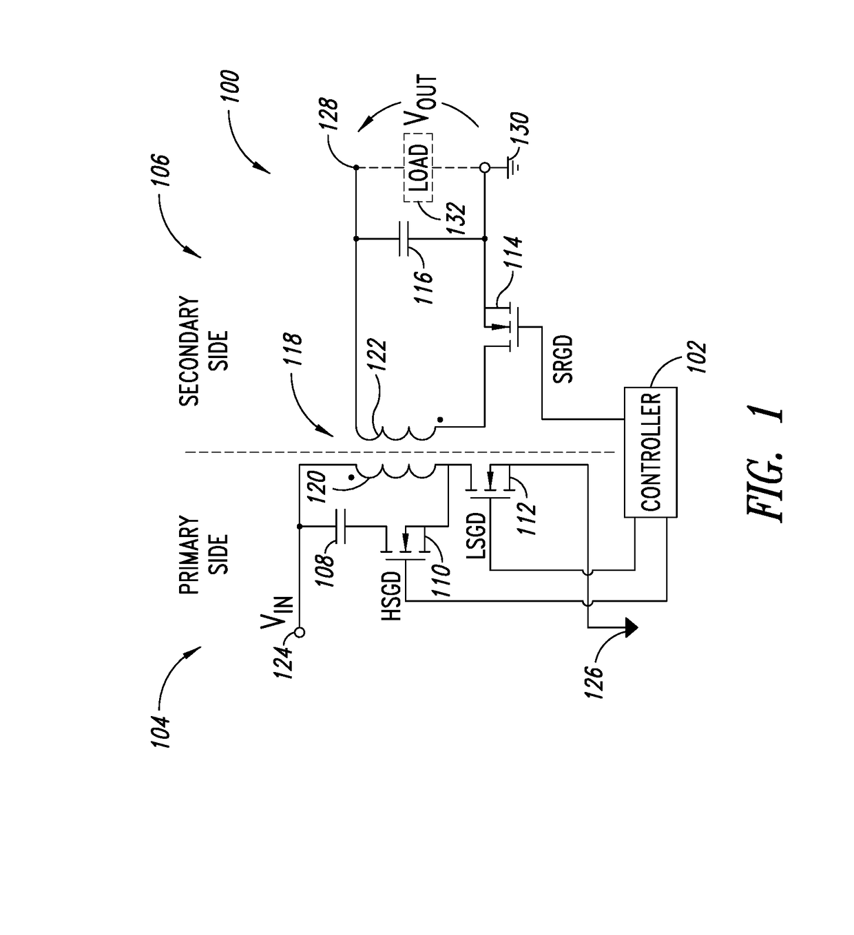
[0023]FIG. 1 shows a circuit diagram of an active clamp flyback converter 100 coupled to a controller 102. The converter 100 has a primary side 104 and a secondary side 106, which may be in galvanically isolated power domains. The converter 100 includes, in the primary side 104, a clamp capacitance 108, a high side transistor 110 and a low side transistor 112. The converter 100 includes, in the secondary side 106, a synchronous rectifier transistor 114 and an output capacitance 116. The converter 100 includes a transformer 118 having a primary winding 120 disposed in the primary side 104 and a secondary winding 122 disposed in the secondary side 106. The controller 102 is distributed over the primary and secondary sides 104, 106 and may have internal galvanic isolation between the primary and secondary sides 104, 106. However, in various embodiments the controller 102 may be in the primary side 104 or the secondary side 106.

[0024]In FIG. 1, the high side transistor 110 is represente...


PUM


Abstract

A method and controller for controlling a converter are provided. The converter is operated in a first phase in which controller logic asserts a first gate drive signal to cause a first transistor of the converter to be conductive and deasserts a second gate drive signal to cause a second transistor of the converter to be non-conductive. In a first deadtime phase and a second phase, the controller logic deasserts both the first and second gate drive signals to cause leakage energy from a leakage inductance of a primary winding of the converter to be transferred to a clamp capacitance of the converter. After the leakage energy is transferred, the converter is operated in a third phase in which the logic asserts the second gate drive signal and deasserts the first gate drive signal.

Description

BACKGROUNDTechnical Field[0001]This disclosure is directed to a controller and a method for controlling an active clamp flyback converter and, in particular, a controller and a method that control the converter while achieving zero voltage switching (ZVS) and minimizing the root mean square (RMS) current of the primary side of the converter.Description of the Related Art[0002]The active clamp flyback converter is a class of switching converters in which a clamp capacitance is used to recover and store energy leaked by a primary side winding or inductance. The energy is then released at the converter output. Conventional techniques for controlling the active clamp flyback converter employ complementary switching in which the primary side winding is energized in a first period and recovered energy is released to the output in a second period. These conventional techniques, however, suffer from a high RMS of the primary side current over the course of the switching cycle, which degrade...

Claims


Application Information

Patent Timeline
IPC IPC(8): H02M1/08H02M3/335H02M1/00
CPCH02M1/083H02M3/33592H02M2001/0009H02M2001/0058H02M1/38H02M1/0058H02M1/385H02M3/33523Y02B70/10H02M1/342H02M1/0009
Inventor BIANCO, ALBERTOADRAGNA, CLAUDIO
Owner STMICROELECTRONICS SRL
Why Eureka
Try Eureka