Wireless power transfer coil system using offset of electric and magnetic coupling for frequency splitting suppression

a technology of electric and magnetic coupling and frequency splitting suppression, which is applied in the direction of transformers/inductance coils/windings/connections, transformers/inductance coils/windings/connections, etc., can solve the problems of reducing system efficiency, reducing the operating life of devices, and reducing the efficiency of the system, so as to maintain high efficiency and reduce the cost of the system. , the effect of not increasing the cost of the system

Inactive Publication Date: 2019-02-26
SOUTH CHINA UNIV OF TECH
View PDF9 Cites 0 Cited by
  • Summary
  • Abstract
  • Description
  • Claims
  • Application Information

AI Technical Summary

Benefits of technology

[0005]A coil system applying to wireless power transfer within a short distance or a medium distance is proposed in the present invention, aiming at overcoming the above disadvantages existing in the prior art. In the present invention, when the distance between coils changes from a long distance to a short distance, capacitive coupling exists between annular metal sheets and inductive coupling exists between the coils. Due to an offset of magnetic and electric coupling, an increasing tendency of a total coupling coefficient is suppressed, so that the frequency splitting is suppressed, and the coupling coefficient is substantially constant within a certain distance, maintaining a high-efficiency power transmission. When the distance changes from the short distance to the long distance, the capacitive coupling between the annular metal sheets decreases sharply, and the coupling between the coils is mainly inductive coupling, which is relatively weak, with no phenomenon of frequency splitting appearing, and still maintaining a high-efficiency transmission. This coil system could realize a high-efficiency power transfer within a certain distance, relying on a self-adaptive adjustment of the magnetic and electric coupling between the coils. Compared with the similar design, it does not increase the complexity of the original circuit system. The system is simpler and is easier to be tested, meanwhile the distance of the capacitive coupling is relatively close, similarly not affecting the power transfer within a long distance, and having a larger variable distance range.
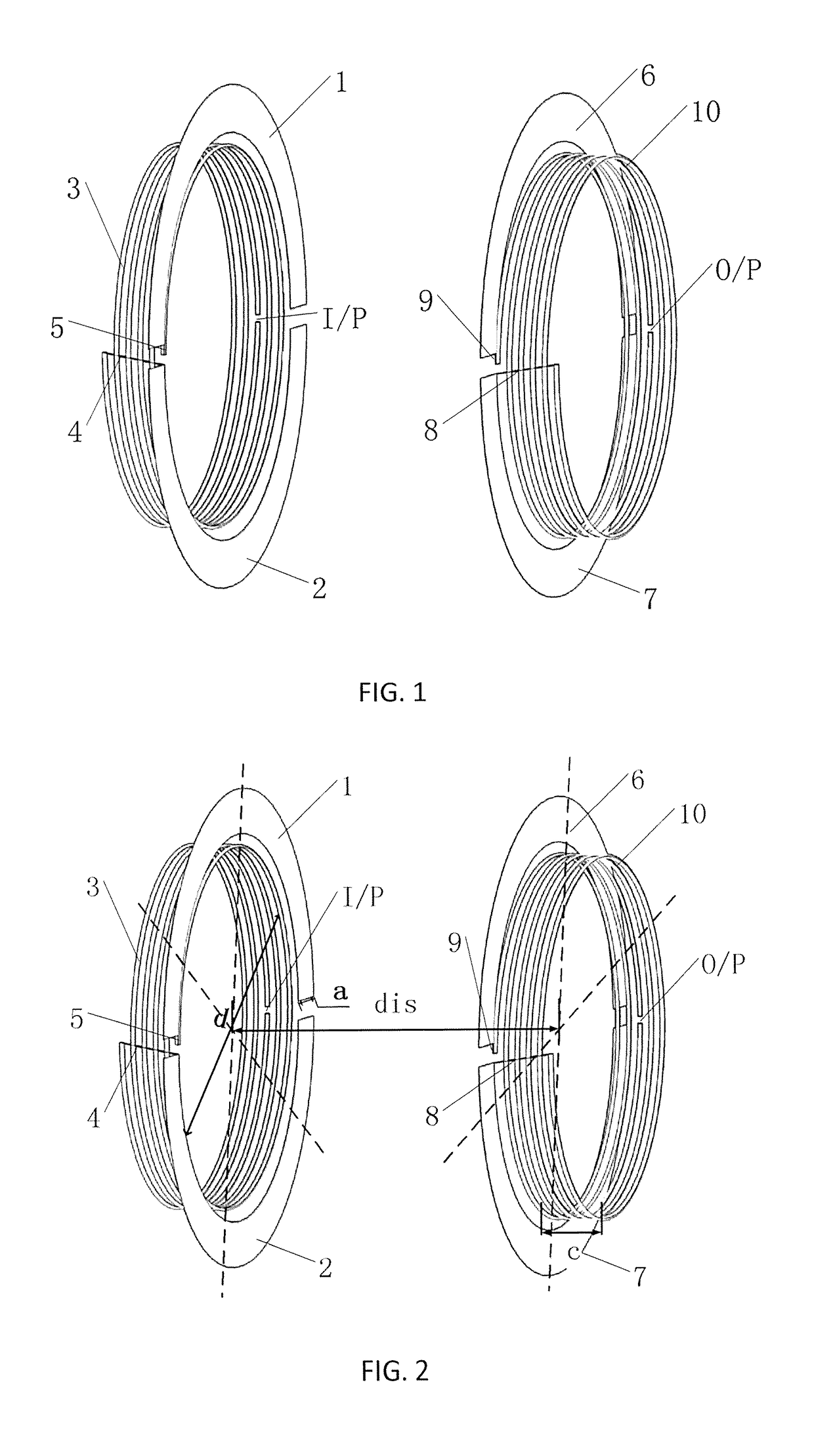
[0008]Further, a loading mode of the first annular metal sheet, the second annular metal sheet, the third annular metal sheet and the fourth annular metal sheet, and a feeding mode of the transmitting coil and a feeding mode of the receiving coil together constitute a sufficient condition for an offset of magnetic and electric coupling. The transmitting coil is wound clockwise, the receiving coil is wound anticlockwise, and the two coils are wound oppositely. The first annular metal sheet loaded at the transmitting coil is wound opposite to the transmitting coil, with its end being connected to an end of the transmitting coil via a wire; the second annular metal sheet loaded at the transmitting coil is wound opposite to the transmitting coil, with its end being connected to the transmitting coil via a wire; the third annular metal sheet loaded at the receiving coil is wound opposite to the receiving coil, with its end being connected to the receiving coil via a wire; and the fourth annular metal sheet loaded at the receiving coil is wound opposite to the receiving coil, with its end being connected to the receiving coil via a wire, which together results in that an electric field vector and a magnetic field vector between the transmitting coil and the receiving coil are opposite, constituting a necessary condition for the offset of magnetic and electric coupling. In addition, the number of turns of the transmitting coil is an odd number, from up to down being a first turn and a last turn, respectively, and the transmitting coil is wound clockwise, with its two ends being open, and a turn in the middle being interrupted from the middle as a feeding port of a high-frequency power source. The number of turns of the receiving coil is an odd number, from up to down being a first turn and a last turn, respectively, and the receiving coil is wound anticlockwise, with its two ends being open, and a turn in the middle being interrupted from the middle as a feeding port for receiving power. The ends of the coils are open in such way, so that electric field effect increases at the ends.
[0009]Further, a resonance mode of the transmitting coil and receiving coil constitutes a basic condition for the offset of magnetic and electric coupling. Lengths of the transmitting coil and the receiving coil are consistent, both being a quarter wavelength of working frequency, so that the coils could be resonant near the working frequency by using the stray capacitance of themselves, and are equivalent to a series resonance. Therefore, the coil system is not necessary to additionally load resonant capacitance, reducing the resonant capacitance of itself as much as possible, thereby improving a mutual capacitance coefficient between the coils, so that it achieves an order of magnitudes same as a mutual inductance system, and thereby the mutual capacitance coefficient and the mutual inductance coefficient are offset mutually, forming the character of the offset of magnetic and electric coupling.
[0010]Further, an expanded transmission distance range depends on widths of the loaded first annular metal sheet, the second annular metal sheet, the third annular metal sheet and the fourth annular metal sheet. A coupling capacitance between the transmitting coil and the receiving coil mainly is mainly constituted by series connection of capacitances between the loaded first annular metal sheet and the third annular metal sheet, and between the second annular metal sheet and the fourth annular metal sheet. In order to maximize the coupling capacitance between the coils to offset energy of coupling inductance, the width of each annular metal sheet maintains consistent, and by adjusting the width, the mutual capacitance coefficient between the coils is adjusted, and thereby an offset degree of the electric coupling to the magnetic coupling is directly adjusted. As the total coupling is equal to the magnetic coupling minus the electric coupling, finally a total coupling coefficient changes gradually with the distance, so that the variable distance range is expanded.
[0013](1) the wireless power transfer coil system according to the present invention could maintain high-efficiency by self-adaptively adjusting the coupling degree according to the transmission distance, which doesn't need to add additional control circuit, therefore the cost of the system will not be increased, meanwhile, the system is simpler and is convenient for debugging and application;
[0014](2) only a section of annular metal sheet with a relative small width is loaded around the coil in the present invention, which maintains high-efficiency in a variable distance, meanwhile makes sure that the volume will not be greatly increased, so that the coils are easier to be fitted to the actual system.

Problems solved by technology

Conventional power transfer mainly depends on a form of wire connection, but wires occupy large amounts of space resources, consume large quantities of metal resources, meanwhile easily produce contacting electric spark, and cause great hidden safety problems to living and life.
In addition, in some utilization occasions, the wires could not be utilized for power transfer, but the using of batteries greatly restricts the operating life of devices.
However, the disadvantage of this system is that a fixed distance is needed, and when the distance changes, the system efficiency will be lowered greatly.
But circuits such as frequency measurement circuit, phase-locked loop circuit and voltage sampling control circuit etc. are needed to be added to the system based on the original WiTricity system, which increases the complexity of the system, and causes some difficulties for realizing debugging and application.
Nevertheless, the antiparallel loops weaken the mutual inductances in the weak coupling region and, consequently, of the extension of the operating distance.

Method used


Image

  • Wireless power transfer coil system using offset of electric and magnetic coupling for frequency splitting suppression
  • Wireless power transfer coil system using offset of electric and magnetic coupling for frequency splitting suppression

Examples


embodiment

[0020]A structure of a wireless power transfer coil system using offset of electric and magnetic coupling for frequency splitting suppression is shown in FIG. 1. Related dimensions are shown in FIG. 2, wherein a thickness of the selected metal sheet is 2 mm, a distance between the coils is dis, and the specific circuit dimensions are selected as follows: the diameter d of the coil=185 mm, the width a of the metal sheet is 25 mm, the thickness c of the coil=30 mm, the diameter r of the coil copper wire=2 mm, and the total dimension is 235 mm×235 mm.

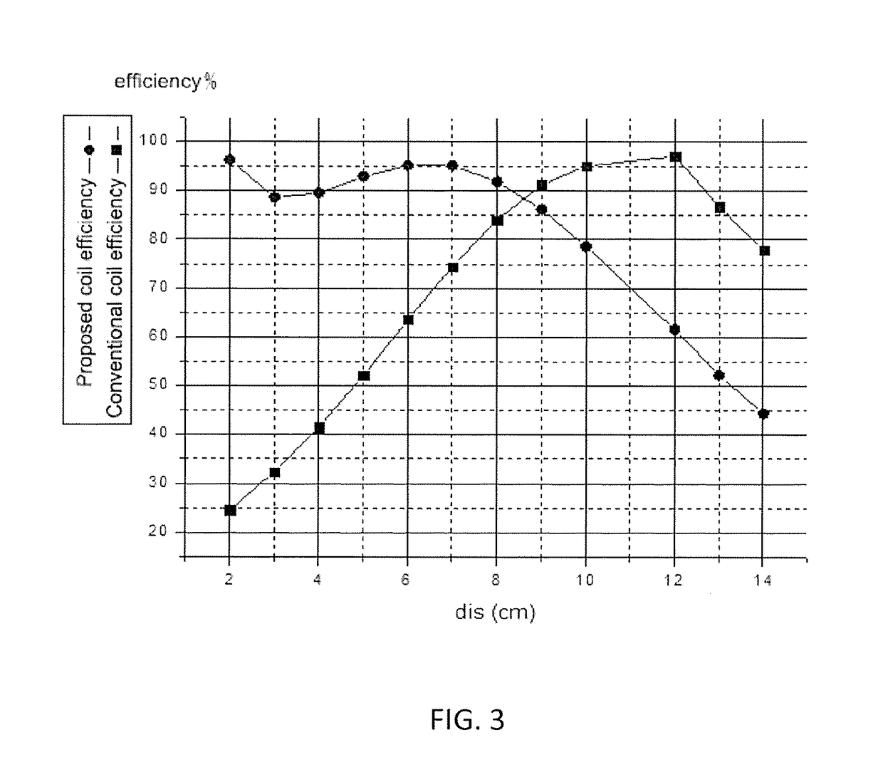
[0021]FIG. 3 is a simulation result of transmission efficiency of the coil system changing with distance, from which it can be seen that, the original coils have an efficiency over 80% only within 8 cm to 14 cm, and the variable distance range is only 6 cm, and the efficiency sharply reduces when the coils are close. However, the improved coils have a transmission efficiency over 80% within 0 to 10 cm, and the variable distance range is 10...


PUM

PropertyMeasurementUnit
distanceaaaaaaaaaa
diameteraaaaaaaaaa
thicknessaaaaaaaaaa

Abstract

A wireless power transfer coil system using offset of electric and magnetic coupling for frequency splitting suppression, which includes one transmitting coil, one receiving coil and four loaded annular metal sheets, is provided. A first annular metal sheet and a second annular metal sheets of the four loaded annular metal sheets are loaded between the transmitting coil and a third and a fourth annular metal sheets of the four loaded annular metal sheets are loaded between the receiving coil to expand a variable distance range of a power transmission. The coil system enables the coils to worked in a state of magnetic and electric coupling. During a process of moving from a long distance to a short distance, a coupling coefficient between the coils changes gradually, but a low coupling degree is still maintained so that a phenomenon of frequency splitting is not produced, thereby maintaining a high-efficiency power transmission within the system.

Description

CROSS-REFERENCE TO RELATED APPLICATION[0001]This application is a 371 application of the International PCT application serial no. PCT / CN2015 / 097979, filed on Dec. 19, 2015, which claims the priority benefit of China application no. 201510786922.4, filed on Nov. 16, 2015. The entirety of each of the abovementioned patent applications is hereby incorporated by reference herein and made a part of this specification.TECHNICAL FIELD[0002]The present invention relates to a technical field of high-efficiency wireless power transfer systems with a variable distance, and specifically relates to a wireless power transfer coil system using offset of electric and magnetic coupling for frequency splitting suppression.BACKGROUND[0003]Conventional power transfer mainly depends on a form of wire connection, but wires occupy large amounts of space resources, consume large quantities of metal resources, meanwhile easily produce contacting electric spark, and cause great hidden safety problems to livi...

Claims


Application Information

Patent Timeline
Patent Type & Authority Patents(United States)
IPC IPC(8): H01F27/34H01F27/28H04B5/00H01F38/14H02J50/12H02J50/70H02J50/10
CPCH01F27/34H01F27/28H01F38/14H02J50/10H02J50/70H04B5/0037H02J50/12H04B5/0075H04B5/0012
Inventor ZHANG, XIUYINXUE, CHENGDAILI, BIN
Owner SOUTH CHINA UNIV OF TECH
Why Eureka
Try Eureka