

Method and apparatus for coherence enhancement of sweep velocity locked lasers via all-electronic upconversion
a technology of all-electronic upconversion and coherence enhancement, which is applied in the direction of laser details, instruments, measurement devices, etc., can solve the problems of distorted measurements in the fourier transform domain, high vibrational noise, bulky design, etc., and achieves the effect of reducing linewidth, small footprint and small footprin
- Summary
- Abstract
- Description
- Claims
- Application Information
AI Technical Summary
Benefits of technology
Problems solved by technology
Method used
Image

Examples
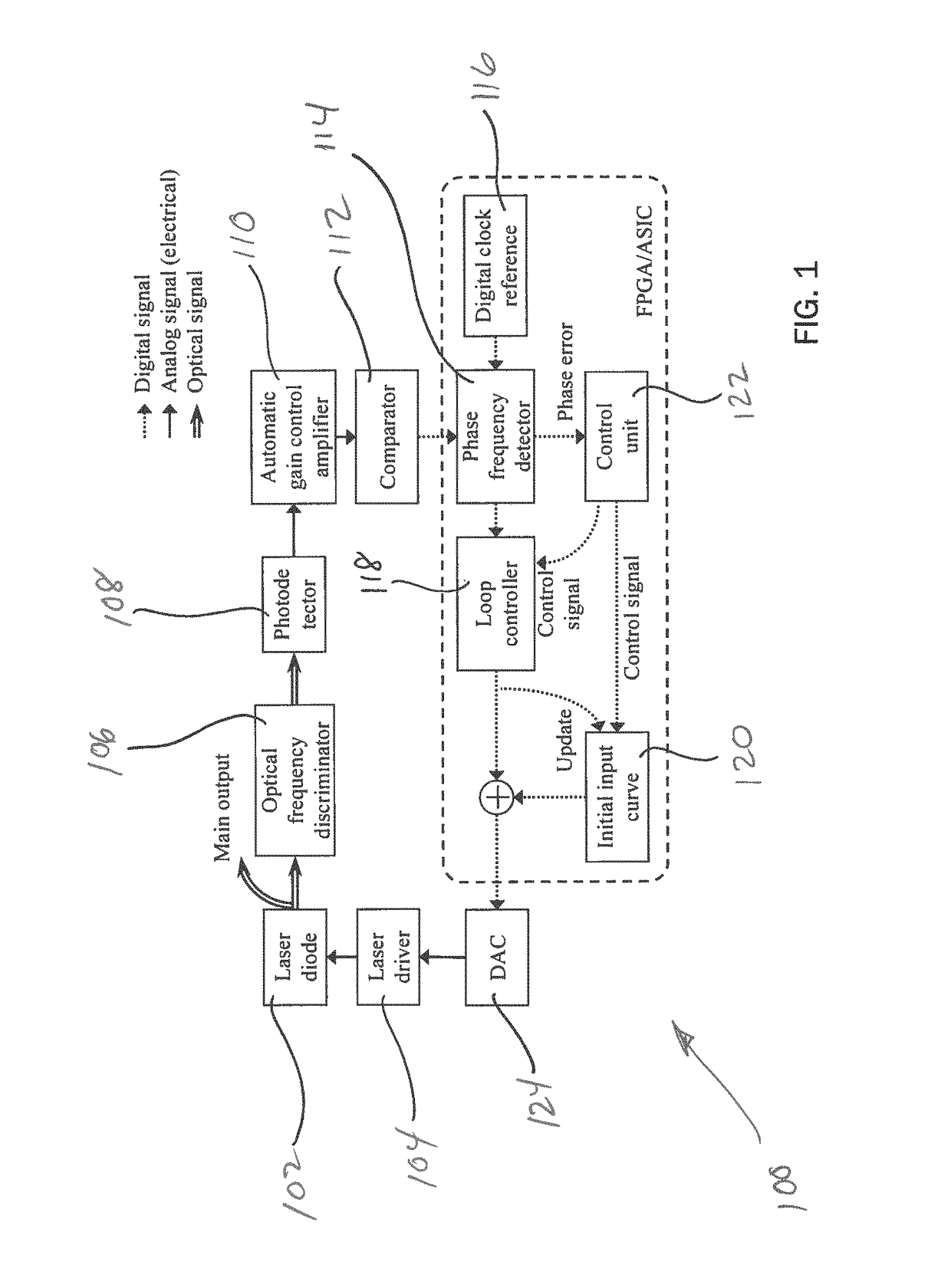
embodiment 100
[0025]FIG. 4 depicts an exemplary architecture of an SV-LLPG generally indicated at 200 with improved coherent length via signal-side band (SSB) modulation method. The general configuration is similar to embodiment 100 with similar components with the exception of an Analog to Digital Converter (ADC) 201 at the output of the AGC 110. The key to improving coherence, or reducing linewidth of the laser output, is to mitigate the phase noise at broader bandwidth. To do so, the loop bandwidth needs to be broadened. However, in the previous design, shown in FIG. 1, the loop bandwidth is limited by the bandwidth of the RF signal, which is typically ranging from a few tens of kHz to a few MHz.
[0026]In order to break this limit, a Single-Sideband (SBB) modulation module 202 is used to up-convert the RF signal from ω to ω+Wc, where ωc is the carrier frequency, which is at least 10 times higher than the RF signal frequency, ω. The up-converted signal is fed into a zero-crossing detector 204 to...
embodiment 200
[0027]FIG. 5 is an exemplary architecture of SV-LLPG generally indicated at 300 with improved coherent length via a direct phase measurement (DPM) method. The general configuration is similar to embodiment 200 with similar components. The essence of this method is also increasing the loop bandwidth of the SV-LLPG. The RF signal, captured by an analog-to-digital converter (ADC) 302, is Hilbert transformed 304 to output instantaneous phase as a function of time. The unwrapped phase 306 is locked to a linear progressive phase ramp function 308, or the reference signal (not shown), to achieve sweep velocity locking. The phase measurement sampling rate is the same as the master clock of the digital chip, which can easily reach 100 MHz. Thus, the loop bandwidth of this method is significantly larger than previously description SV-LLPG in FIG. 1.
[0028]FIG. 6 is an exemplary architecture of SV-LLPG generally indicated at 400 with improved coherent length via multiple loop locking method (SS...
embodiment 300
[0029]FIG. 8 is an exemplary architecture of SV-LLPG generally indicated at 500 with improved coherent length via multiple loop locking method (DPM as fast loop). The general configuration is similar to embodiment 300 with similar components. This approach holds the advantage of simultaneously providing fast and slow servo control loops 502 and 504 to maximize the locking performance at both low frequency range and high frequency range. It is worth noting that the control loop signals from both fast loop 502 and slow loop 504 can be added together via a digital summator 506, shown in FIG. 8, or in an analog adder (not shown), or bias Tee 508, built in the laser driver 104, shown in FIG. 9. In the bias Tee configuration, there is a separate DAC 124 for each of the fast control loop 502 and the slow control loop 504.
[0030]It is worth noting that the number of loops in disclosed multi-loop architecture is not limited to two. Also, a series of combination of SSB modulation and DPM metho...
PUM
 Abstract
Description
Claims
Application Information