Laser source with reduced linewidth

a laser source and linewidth technology, applied in the direction of laser optical resonator construction, laser details, active medium shape and construction, etc., can solve the problems of not always being able to obtain the requisite width in this way, undesirable for a large number of applications, and weak back-projection of rayleigh type, etc., to reduce the linewidth, reduce the laser linewidth, and reduce the effect of reflection

Active Publication Date: 2017-07-18
THALES SA
View PDF10 Cites 0 Cited by
  • Summary
  • Abstract
  • Description
  • Claims
  • Application Information

AI Technical Summary

Benefits of technology

[0012]Such reflectors make it possible to obtain much stronger reflections than those obtained by the Rayleigh scattering centres of an optical fibre. To reduce the linewidth of the laser, it is then possible to use much shorter waveguides, of a few centimetres or less instead of kilometres of optical fibres. The device, which includes the source and the waveguide, is therefore much more compact. Furthermore, the random nature of the distribution of the reflectors makes it possible to reduce the linewidth without creating pronounced resonances in the phase noise spectrum and in the optical emission spectrum of the laser. Finally, such a device makes it possible not only to reduce the width of a single line in the case of a single-wavelength laser source, but also to reduce the width of each line of a multi-wavelength laser source.

Problems solved by technology

But it is not always possible to obtain the requisite width in this way.
However, these resonances, which correspond to those of the external cavity formed by the external mirror 2 and the exit face 11 of the laser source, are undesirable for a large number of applications.
But this back-projection of Rayleigh type is very weak.
As a result the laser device which incorporates the laser source and an optical fibre of such a length is very bulky.
Furthermore, temperature variations and vibrations induce fluctuations in the Rayleigh scattering, which translate into undesirable fluctuations in the frequency of the laser.
Furthermore, all these solutions apply to single-wavelength sources only.

Method used


Image

  • Laser source with reduced linewidth
  • Laser source with reduced linewidth
  • Laser source with reduced linewidth

Examples


first embodiment

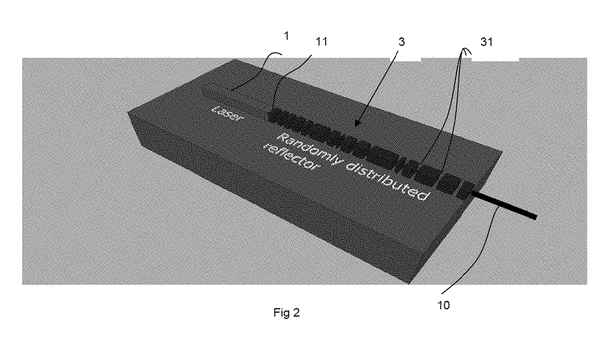
[0022]An example of a laser device according to the invention will now be described as it relates to FIG. 2.

[0023]A laser source 1 is coupled with a single-mode waveguide 3 which is integrated monolithically with the laser source: they are both made from the same base material. This coupling between the laser source and the guide can be achieved using several methods, among which mention may be made of end-to-end coupling, and coupling by a mode-size adapter. Reflectors 31 are etched into the waveguide in the form of trenches randomly distributed along the waveguide. The trenches can all have the same length but not necessarily; the length of the trenches (considered along the direction of propagation of the laser 10) is between 50 and 500 nm. The base material is for example based on InP, GaAs or is a photonic integration platform combining a III-V material with silicon for example. In the latter case, it is a hybrid III-V laser source 1. The reflectors 31 are etched into the silic...

second embodiment

[0024]An example of a laser device according to the invention is shown in FIGS. 3a and 3b with two variants. According to this embodiment, the waveguide 3 is an optical fibre; the laser source 1 and the optical fibre 3 are produced separately, then coupled with each other by means of a coupling device 4. The reflectors 31 are produced in the optical fibre 3, for example by UV illumination through a mask in such a way as to locally modify the refractive index of the optical fibre and thus obtain localized reflectors, as is done in the manufacture of Bragg arrays. The patterns in the mask are randomly distributed in such a way as to obtain a random location of the reflectors along the optical fibre. The laser source can be a solid-state laser such as an erbium-doped fibre laser or a semiconductor laser.

[0025]The laser source and the optical fibre can be incorporated into one and the same housing; they are then coupled with each other, for example by means of a lens 32, as is the case ...


PUM


Abstract

In the field of narrow linewidth laser sources and a laser device that comprises a laser source and a waveguide of determined refractive index with which it is coupled, a waveguide is single-mode and includes at least four reflectors in the form of trenches etched into the waveguide and irregularly distributed along the waveguide, the distance separating two neighbouring reflectors being above 1 μm, and the waveguide and the laser source have respective lengths such that the length of waveguide over which the reflectors are located is greater than the length of the laser source itself.

Description

CROSS-REFERENCE TO RELATED APPLICATION[0001]This application claims priority to foreign French patent application No. FR 1302929, filed on Dec. 13, 2013, the disclosure of which is incorporated by reference in its entirety.FIELD OF THE INVENTION[0002]The field of the invention is that of laser sources with reduced linewidths.BACKGROUND[0003]The linewidth of a laser is of prime importance for a certain number of applications. Mention may be made, for example, of coherent optical transmission systems with high transmission rates, for which a linewidth below 300 kHz is required when used in QAM (Quadrature Amplitude Modulation) mode. To generate a millimetre-wavelength or terahertz wave using the beating of two single-wavelength lasers, the linewidth of these lasers determines the linewidth of the millimetre-wavelength or terahertz wave.[0004]Several solutions exist to reduce the linewidth of a single-wavelength laser source.[0005]The first is of course to design a laser source so that...

Claims


Application Information

Patent Timeline
Patent Type & Authority Patents(United States)
IPC IPC(8): H01S5/00H01S5/026H01S3/067H01S5/065H01S3/10H01S5/12H01S5/40
CPCH01S5/0268H01S3/0675H01S5/026H01S5/0656H01S3/10084H01S5/1215H01S5/4087
Inventor DUAN, GUANG-HUAVAN DIJK, FREDERICKERVELLA, GAEL
Owner THALES SA
Why Eureka
Try Eureka