

Current-mode PUF circuit based on reference current source
- Summary
- Abstract
- Description
- Claims
- Application Information
AI Technical Summary
Benefits of technology
Problems solved by technology
Method used
Image

Examples
first embodiment
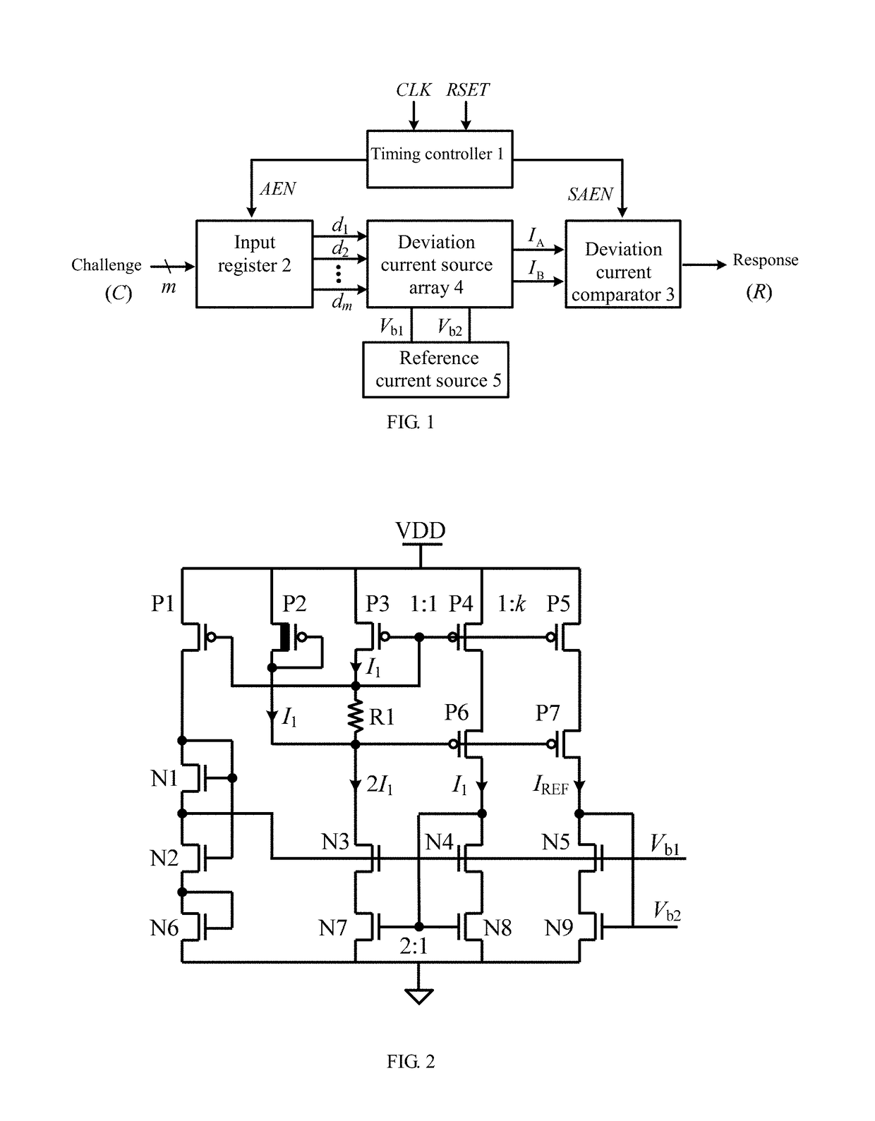
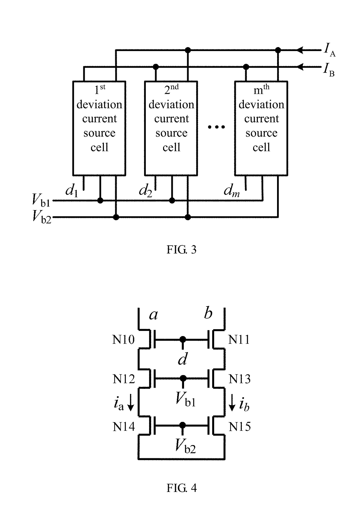
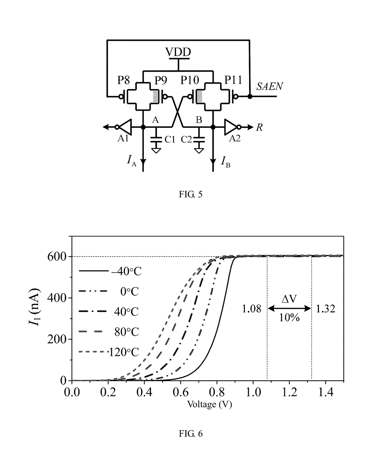
[0030]As is shown in FIGS. 1-4, a current-mode PUF circuit based on a reference current source 5 comprises a timing controller 1, an input register 2, a deviation current comparator 3 and a deviation signal generation circuit. The timing controller 1 is provided with a clock terminal, a setting terminal, a 1st output terminal and a 2nd output terminal. Clock control signals are to be accessed to the clock terminal of the timing controller 1. Setting signals are to be accessed to the setting terminal of the timing controller 1. The input register 2 is provided with an enable terminal, an input terminal and m output terminals, and m is an integer greater than or equal to 2. The deviation current comparator 3 is provided with a power terminal, an enable terminal, a 1st input terminal, a 2nd input terminal and an output terminal. The 1st output terminal of the timing controller 1 is connected to the enable terminal of the input register 2. The 2nd output terminal of the timing controlle...
second embodiment
[0031]As is shown in FIGS. 1-4, a current-mode PUF circuit based on a reference current source 5 comprises a timing controller 1, an input register 2, a deviation current comparator 3 and a deviation signal generation circuit. The timing controller 1 is provided with a clock terminal, a setting terminal, a 1st output terminal and a 2nd output terminal. Clock controls signals are to be accessed to the clock terminal of the timing controller 1. Setting signals are to be accessed to the setting terminal of the timing controller 1. The input register 2 is provided with an enable terminal, an input terminal and m output terminals, and in is an integer greater than or equal to 2. The deviation current comparator 3 is provided with a power terminal, an enable terminal, a 1st input terminal, a 2nd input terminal and an output terminal. The 1st output terminal of the timing controller 1 is connected to the enable terminal of the input register 2. The 2nd output terminal of the timing control...
PUM
 Abstract
Description
Claims
Application Information