Coil device and transcranial magnetic stimulation system
a transcranial magnetic stimulation and coil device technology, applied in the field of coil device and transcranial magnetic stimulation system, can solve the problems of ineffective drug therapy for these diseases, the weight of conventional magnetic stimulation devices is about 70 kg and is available, and the treatment requires a craniotomy, so as to achieve the effect of efficient collection and improved positioning accuracy of coil devices
- Summary
- Abstract
- Description
- Claims
- Application Information
AI Technical Summary
Benefits of technology
Problems solved by technology
Method used
Image
Examples
first embodiment
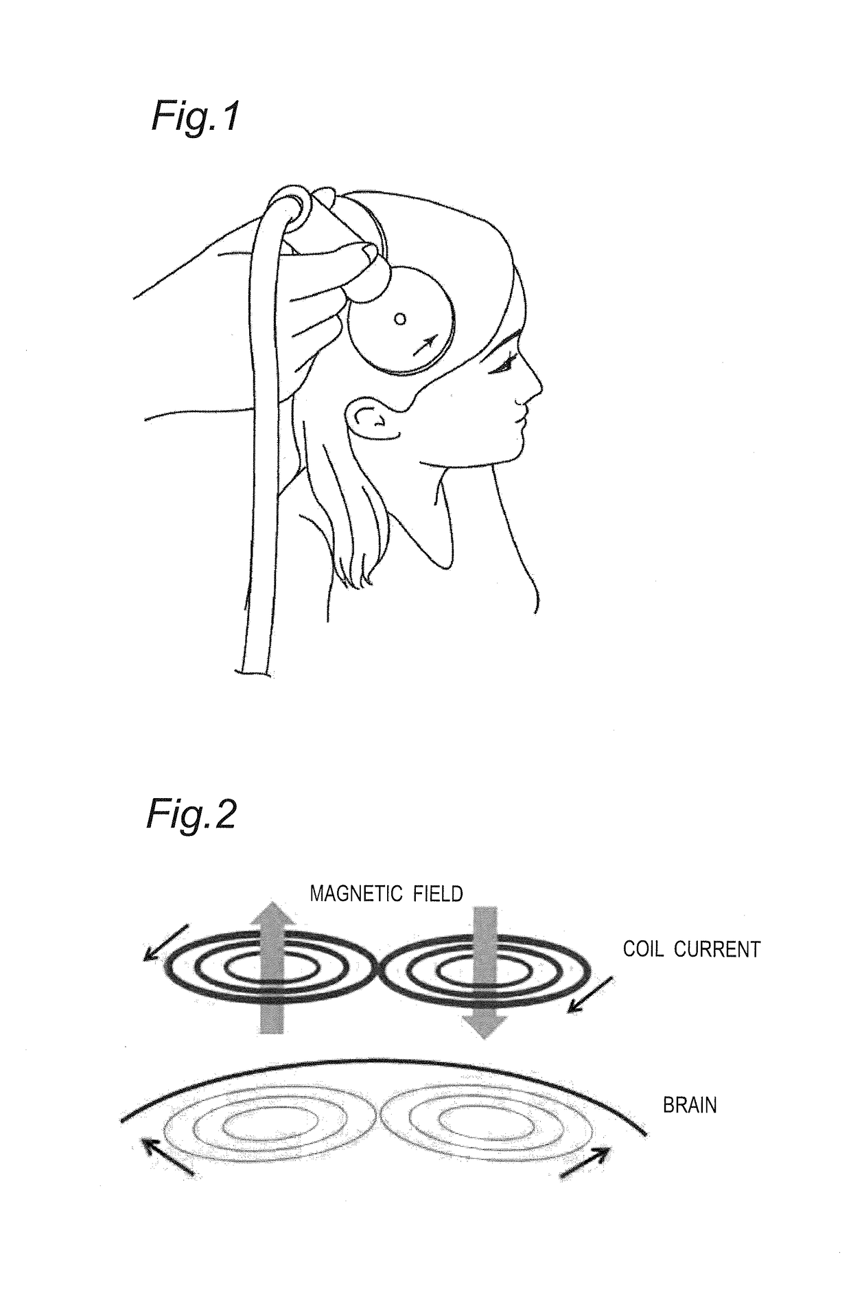
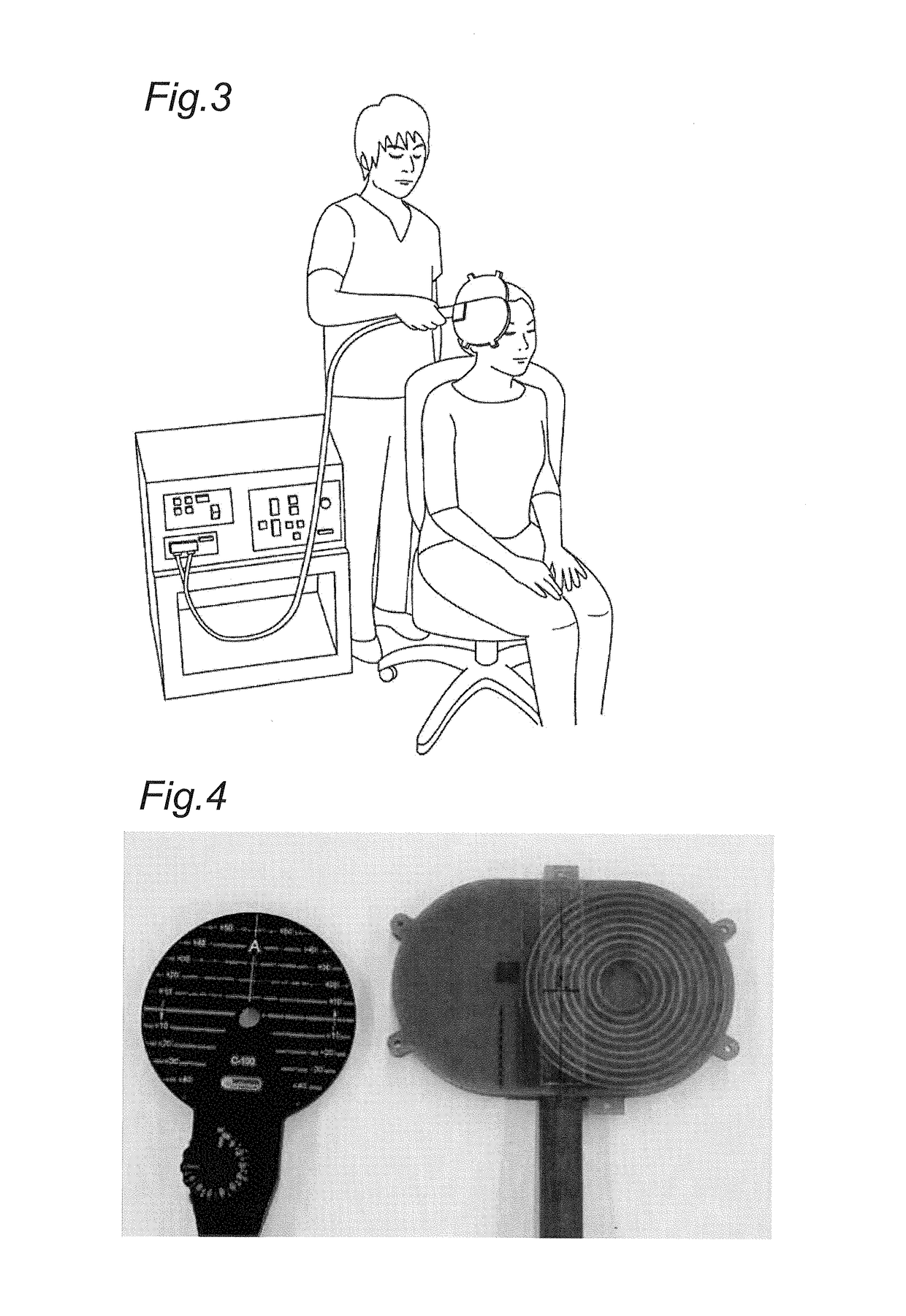
[0112]Referring to FIG. 22, a transcranial magnetic stimulation system (hereinafter simply referred to as a “system”) 1 has a magnetic stimulation device 3 applying a magnetic stimulation to the brain of a patient 2 supported by a support mechanism not shown (e.g., a chair, a bed).
[0113]The magnetic stimulation device 3 has a coil unit (coil device) 4 forming a dynamic magnetic field for applying the magnetic stimulation to a certain site of the brain of the patient 2. As shown, the coil unit 4 is preferably supported by a proper supporting unit (not shown) to enable movement along a head surface of the patient 2 and positioning at an arbitrary position.
[0114]The coil unit 4 includes a coil 5 (see FIGS. 25A-25C). The coil 5 is connected through a cable 6 to a drive unit 7. The drive unit 7 includes a drive circuit 8 (see FIG. 24) described later, and the coil 5 is connected to the drive circuit 8.
[0115]As shown in FIG. 24, the drive circuit 8 has a power circuit 12 converting an out...
second embodiment
[0123]FIGS. 26A to 26C show a coil unit 104 of a second embodiment. In this coil unit 104, the bottom wall 22 of the spool 21, particularly, the outer surface portion 22 of the bottom wall 22 (a spool outer surface) contacting with the coil 5 is recessed in a concave shape in the direction from the lower side toward the upper side of the figures (in the direction away from the head) as is the case with the ceiling wall 23 of the spool 21. Specifically, the cross sections of the bottom wall along the vertical plane including the neutral axis 24 and the vertical plane orthogonal thereto form curved surfaces recessed upward in a concave shape. The curvature of the outer surface portion 22 is obviously smaller than the curvature of the outer surface portion 23a of the ceiling wall 23 (the spool outer surface). The coil 5 is disposed in a curved shape in accordance with the curved bottom wall 22 and is covered on the outer side with the curved bottom housing portion 42. The curvature of ...
third embodiment
[0125]FIGS. 27A and 27B show a coil unit 204 of a third embodiment. In this coil unit 204, an outer surface of the bottom housing portion 42 (a surface facing the patient's head) is recessed in a concave shape in the direction from the lower side toward the upper side of the figures (in the direction away from the head). Specifically, a bottom surface of the bottom housing portion 42 along the vertical plane including the neutral axis 24 and the vertical plane orthogonal thereto forms a curved surface recessed upward in a convex shape. The curvature of the curved surfaces, particularly, the curvature of the bottom housing portion 42 on the outermost layer preferably substantially matches the head shape on which the coil unit 104 is placed. The other constituent elements are the same as those of the first embodiment described above.
[0126]According to the coil unit 204 of the second embodiment configured as described above, the coil unit 204 can be disposed substantially exactly along...
PUM
 Abstract
Description
Claims
Application Information
 - R&D
- Intellectual Property
- Life Sciences
- Materials
- Tech Scout
- Unparalleled Data Quality
- Higher Quality Content
- 60% Fewer Hallucinations
Browse by: Latest US Patents, China's latest patents, Technical Efficacy Thesaurus, Application Domain, Technology Topic, Popular Technical Reports.
© 2025 PatSnap. All rights reserved.Legal|Privacy policy|Modern Slavery Act Transparency Statement|Sitemap|About US| Contact US: help@patsnap.com


