
High frequency heat treatment method of ultra-high strength parts

a high-frequency heat treatment and parts technology, applied in heat treatment apparatus, process efficiency improvement, manufacturing tools, etc., can solve problems such as button fracture or interfacial fracture, button deformation or button fracture, etc., to achieve ultra-high strength, improve the subsequent welding strength of parts, and ultra-high strength

Inactive Publication Date: 2019-03-26
HYUNDAI MOTOR CO LTD
View PDF10 Cites 0 Cited by
  • Summary
  • Abstract
  • Description
  • Claims
  • Application Information

AI Technical Summary

Benefits of technology

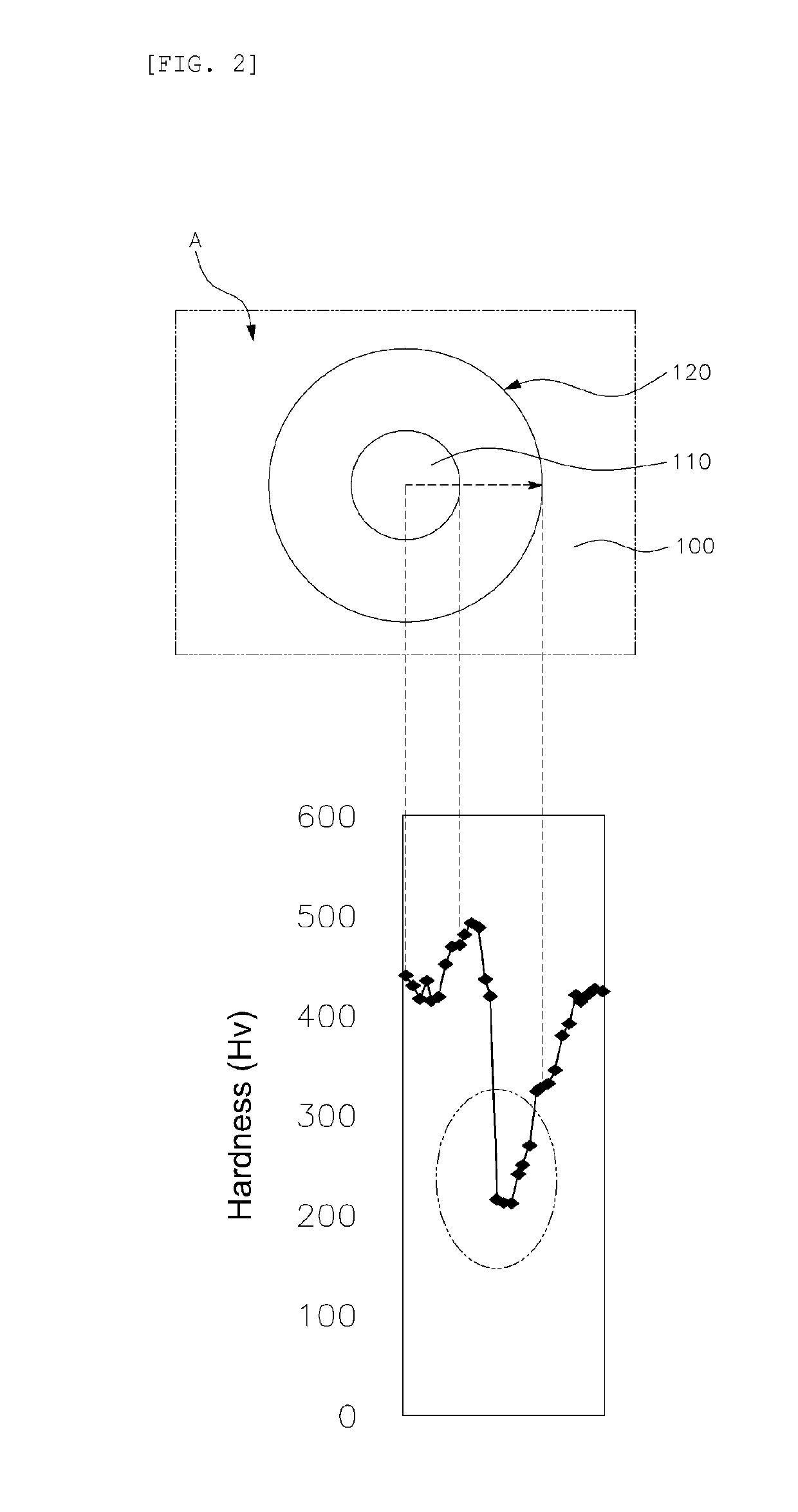
The method significantly increases the elongation ratio and tensile strength of the parts, transforming them from a brittle martensite structure to a softer ferrite-pearlite structure, enhancing energy absorption and impact stability, and preventing brittle fractures, thus improving crash stability without the use of structural adhesives.

Problems solved by technology

However, when broadside collision accidents occur, injury is generally caused by vehicle body deformation.
Thus, the above-noted safety mechanisms do not provide a fundamental solution.
Thus, while the hot-stamping-treated parts have an advantage of high strength, there is a problem in that the ultra-high strength parts are fractured without plastic deformation when external force is applied because a tendency for brittle fracture generally increases with increasing material strength.
This occurs even though a crack is generated at the welding zone of the parts.
On the other hand, a button fracture or interfacial fracture is generated due to insufficient energy absorption (unlike the plug fracture) because a nugget or an attaching point of the welding zone is directly cut.
Further, because the welding zone of the ultra-high strength parts has a lower energy absorbing efficiency than the parts welding zone before the hot-stamping treatment, there is a problem in that a structural adhesive for complementing welding strength is generally applied to a flange of the hot-stamping-treated parts in addition to welding in order to improve the efficiency.

Method used


Image

  • High frequency heat treatment method of ultra-high strength parts
  • High frequency heat treatment method of ultra-high strength parts
  • High frequency heat treatment method of ultra-high strength parts

Examples


Embodiment Construction

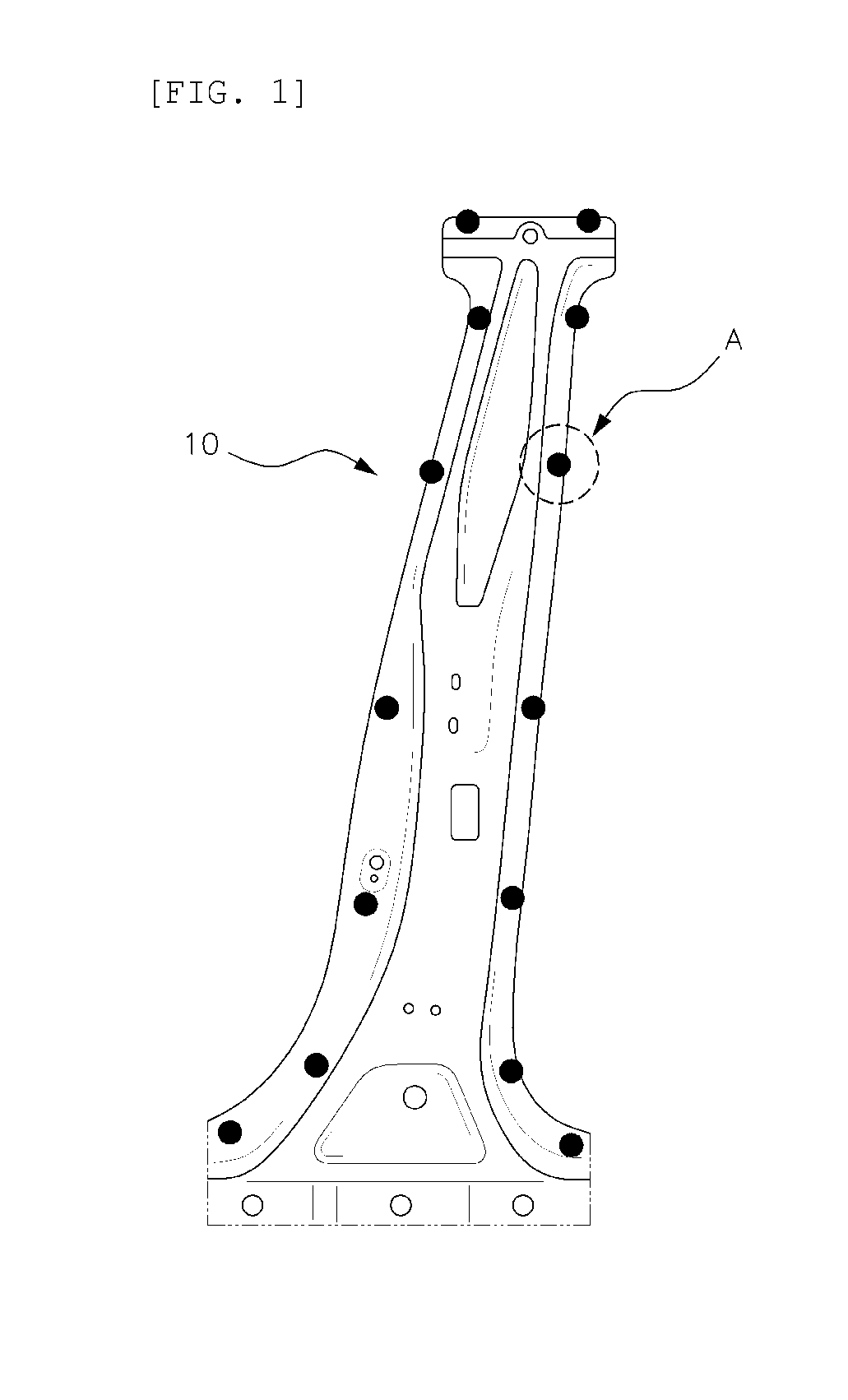
[0039]Hereinafter the present invention will be described in detail with reference to the accompanying drawings and described below.

[0040]It is understood that the term “vehicle” or “vehicular” or other similar term as used herein is inclusive of motor vehicles in general such as passenger automobiles including sports utility vehicles (SUV), buses, trucks, various commercial vehicles, watercraft including a variety of boats and ships, aircraft, and the like, and includes hybrid vehicles, electric vehicles, plug-in hybrid electric vehicles, hydrogen-powered vehicles and other alternative fuel vehicles (e.g. fuels derived from resources other than petroleum). As referred to herein, a hybrid vehicle is a vehicle that has two or more sources of power, for example both gasoline-powered and electric-powered vehicles.

[0041]The terminology used herein is for the purpose of describing particular embodiments only and is not intended to be limiting of the invention. As used herein, the singula...


PUM

PropertyMeasurementUnit
temperatureaaaaaaaaaa
elongation ratioaaaaaaaaaa
tensile strengthaaaaaaaaaa

Abstract

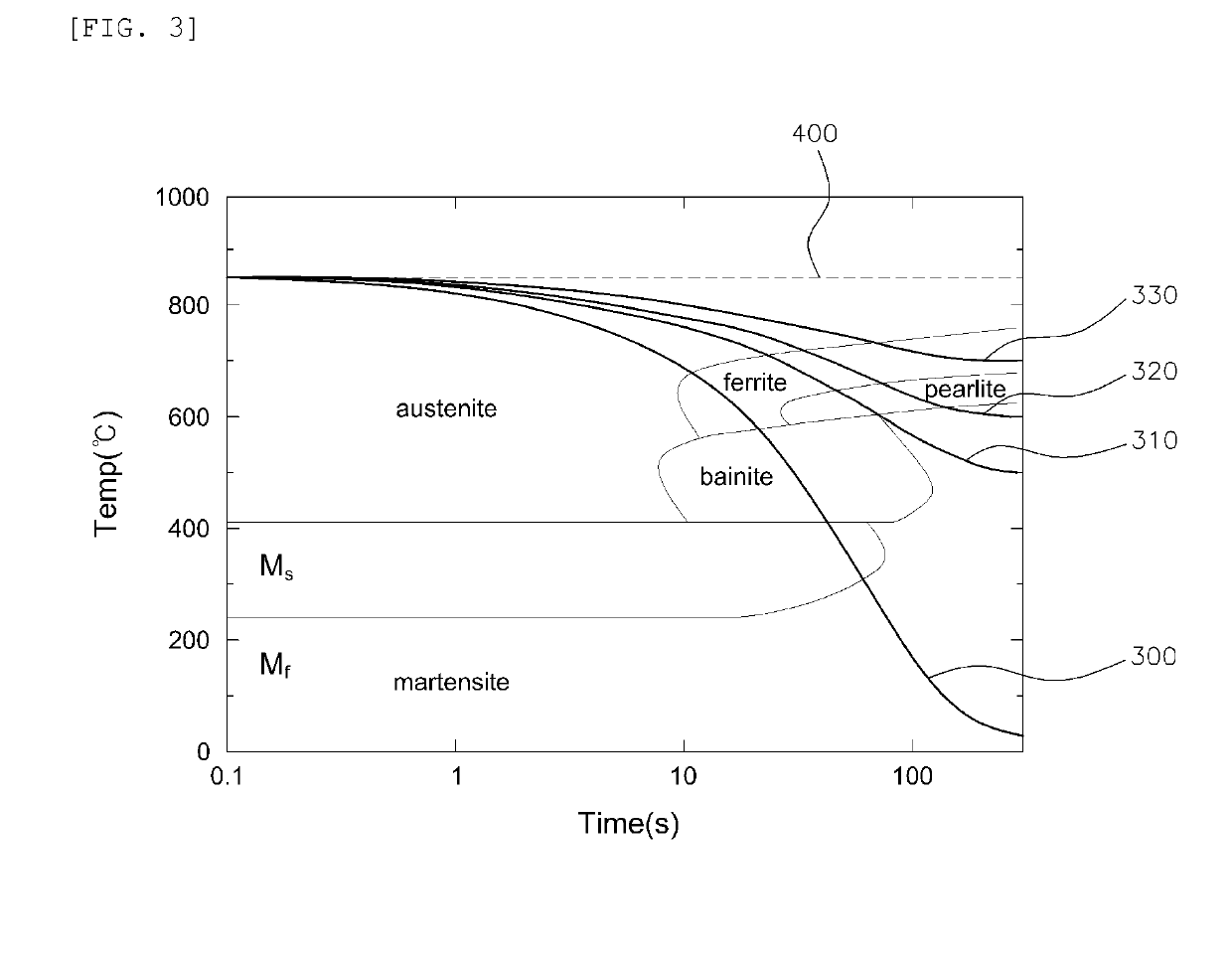
Disclosed is a high frequency heat treatment method of hot-stamping-treated ultra-high strength parts, which comprises: a first step of heating the parts until the temperature of a heat treatment zone thereof becomes the AC3 transformation point or higher; a second step of maintaining the temperature until phase transformation of the heat treatment zone to austenite is completed; and a third step of cooling the heat treatment zone to transform the structure thereof to ferrite-pearlite. The present method improves the energy absorbing efficiency by increasing the parts' elongation ratio by locally forming a softening structure which absorbs energy.

Description

CROSS-REFERENCE TO RELATED APPLICATIONS[0001]This application claims priority under 35 U.S.C. § 119 to Korean Patent Application No. 10-2012-55833, filed on May 25, 2012, in the Korean Intellectual Property Office, the disclosure of which is incorporated herein by reference in its entiretyBACKGROUND OF THE INVENTION1. Field of the Invention[0002]The present invention relates to a method for high frequency heat treatment of ultra-high strength parts, and more particularly, to a heat treatment method that improves energy absorbing efficiency by locally conducting high frequency heat treatment to a heat treatment zone of the part in a hot-stamping process for forming the ultra-high strength parts.2. Description of the Related Art[0003]Areas of heavy interest in the development of vehicles include improvements in crash stability, making the vehicles more lightweight, and reducing costs. In particularly, many safety mechanisms for reducing the degree of injury to passengers during broads...

Claims


Application Information

Patent Timeline
Patent Type & Authority Patents(United States)
IPC IPC(8): C21D6/00C21D7/13C21D1/19C21D1/42C21D1/673C22C1/02C22C38/00C22C38/02C22C38/04
CPCC21D6/008C21D1/42C21D1/673C21D6/005C21D7/13C22C1/02C22C38/002C22C38/02C22C38/04C21D1/19Y02P10/253C21D2211/001C21D2211/005C21D2211/009C21D2221/00Y02P10/25
Inventor HONG, SEUNG-HYUNYOO, JI-HONG
Owner HYUNDAI MOTOR CO LTD
Learn More