Interferometric optical fibre sensor system and method of interrogation

a sensor system and optical fibre technology, applied in the field of interferometric optical fibre sensor systems, can solve the problems of reducing the dynamic range and the sensor phase resolution, and the limited sensor phase resolution of distributed interferometric sensing based on rayleigh scattering of the fibre, and achieves a large dynamic range and high sensor phase resolution

Active Publication Date: 2019-04-02
OPTOPLAN
View PDF21 Cites 15 Cited by
  • Summary
  • Abstract
  • Description
  • Claims
  • Application Information

AI Technical Summary

Benefits of technology

[0012]It is an objective of the present innovation to overcome the presented limitations in the prior art. In particular, it is an objective to provide multiplexing of a large number of interferometric sensors along a fibre, while at the same time obtaining high sensor phase resolution, and large dynamic range.

Problems solved by technology

This will reduced the dynamic range and the sensor phase resolution due to lower time averaged optical power at the receiver.
Distributed interferometric sensing based on the Rayleigh scattering of the fibre provide limited sensor phase resolution due to the very low optical power levels reflected back to the receiver.

Method used


Image

  • Interferometric optical fibre sensor system and method of interrogation
  • Interferometric optical fibre sensor system and method of interrogation
  • Interferometric optical fibre sensor system and method of interrogation

Examples


Embodiment Construction

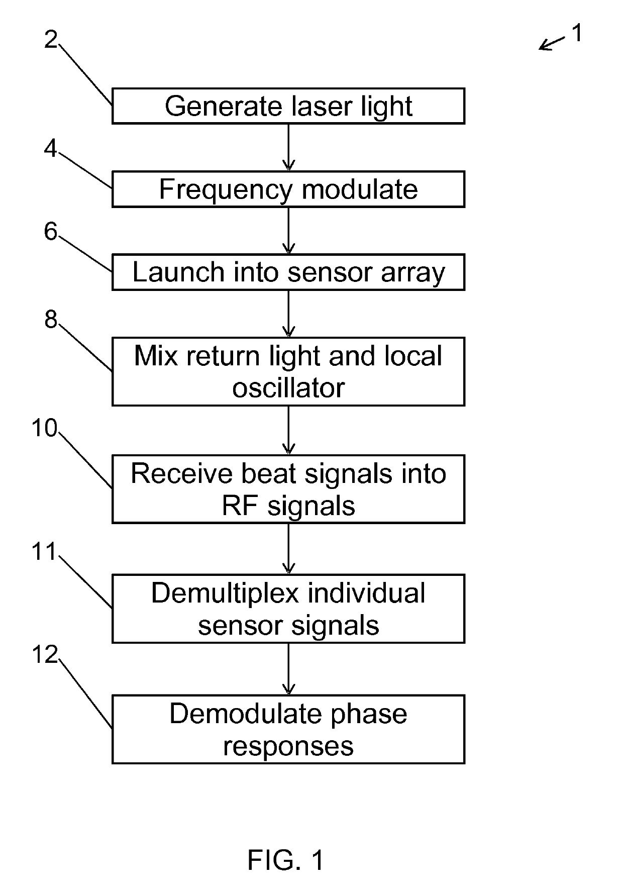
[0079]FIG. 1 illustrates the method 1 of interrogating an interferometric optical fibre sensor system according to the invention. First, interrogation light 2 is generated with a source laser. The laser may be of the continuous wave (CW) type. The interrogation light is frequency modulated 4 in a continuous and repeated manner, as defined above, to produce a swept interrogation light signal. The step of frequency modulation 4 may be performed in different ways, such as direct modulation of the laser source or modulation external to the laser source. External modulation may preferably be performed with an acousto-optic modulator (AOM). The swept interrogation light signal is then launched 6 into the optical fibre sensor array comprising at least two reflectors. Thus, the light launched will have a frequency which is dependent on the launch time, due to the sweep. Therefore, light being reflected from the reflectors at different positions along the sensor array will have different fre...


PUM


Abstract

The invention relates to a method of interrogating an interferometric optical fiber sensor system including a laser source configured to generate interrogation light and a sensor array with at least a first reflector and a second reflector. The method includes continuously and repeatedly frequency sweeping the interrogation light from the laser source within a sweep bandwidth (SWB) over a sweep duration (tsw) with a substantially constant sweep rate r=SBW / tsw to produce a swept interrogation light signal, launching the swept interrogation light signal into the sensor array, detecting reflected signals being returned from the sensor array by each of the reflectors, respectively, wherein detection includes mixing a return light signal from the sensor array with a local oscillator signal onto an optical receiver to produce an electrical radio frequency signal, demultiplexing the electrical radio frequency signal into a first signal channel and a second signal channel, corresponding to the first and second reflector, respectively, demodulating each of the first and second signal channel into a first phase response from the first reflector and a second phase response from the second reflector, and subtracting the first phase response from the second phase response to obtain a sensor phase signal.

Description

CROSS-REFERENCE TO RELATED APPLICATIONS[0001]This application is based on and claims the benefit of European Patent Application No. 14166237.9, filed Apr. 28, 2014, and International Patent Application No. PCT / EP2015 / 059257, filed Apr. 28, 2015, both of which are hereby incorporated herein by reference in their entirety.FIELD OF THE INVENTION[0002]The present invention relates to an interferometric optical fibre sensor system and a method of interrogating an interferometric optical fibre sensor system.BACKGROUND OF THE INVENTION[0003]Optical fibre sensor systems have been deployed in many different applications due to their general distributed nature. Such systems enable that measurements may be made either distributed, or quasi-distributed, i.e. in a potentially large number of points along the fibre. Furthermore, optical fibre sensors in general lend themselves to being multiplexed along a single fibre, thus potentially reducing number of fibres and complexity and bulky lead-in ca...

Claims


Application Information

Patent Timeline
Patent Type & Authority Patents(United States)
IPC IPC(8): G01B9/02G01D5/26
CPCG01D5/266G01D5/268G01B9/02G01B2290/70G01D5/35306G01D5/35316
Inventor RONNEKLEIV, ERLENDWAAGAARD, OLE HENRIK
Owner OPTOPLAN
Why Eureka
Try Eureka