Steered current source for single-ended class-A amplifier

a current source and amplifier technology, applied in the field of audio amplifiers, can solve the problems of reduced efficiency, unsatisfactory sound quality and performance of transistors and integrated circuits in audio equipment (e.g., stereo amplifiers), and inability to meet the sound quality and performance of stereo amplifiers, and achieve the effect of increasing power

Active Publication Date: 2019-04-09
WESTERN ELECTRIC EXPORT CORP
View PDF5 Cites 1 Cited by
  • Summary
  • Abstract
  • Description
  • Claims
  • Application Information

AI Technical Summary

Benefits of technology

[0018]Accordingly, a need exists for single-ended Class-A amplifier circuit that provides increased power to a load without stressing a vacuum tube or other amplification component.

Problems solved by technology

With the advent of transistors followed by integrated circuits, vacuum tubes fell into disuse such that few, if any, modern televisions, radios, and similar electronic devices use vacuum tubes.
However, a substantial group of “true” audiophiles consider the sound quality and performance of transistors and integrated circuits in audio equipment (e.g., stereo amplifiers) to be unsatisfactory because the sound from such modern amplifies tends to be cold and sterile.
In general, a push-pull amplifier provides better efficiency than a single-ended amplifier, however, many advocates of single-ended amplifiers assert that single-ended amplifiers provide a better sound but at a cost of reduced efficiency.
Furthermore, singled-ended amplifiers are limited by the amount of power that can be provided by a singled tube without overheating the tube.

Method used


Image

  • Steered current source for single-ended class-A amplifier
  • Steered current source for single-ended class-A amplifier
  • Steered current source for single-ended class-A amplifier

Examples


Embodiment Construction

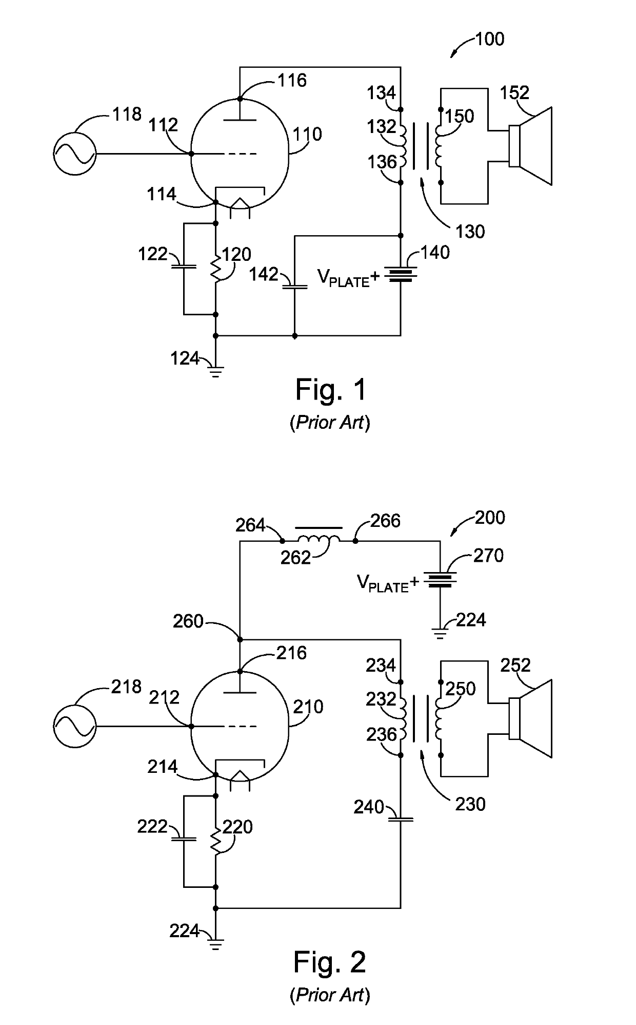
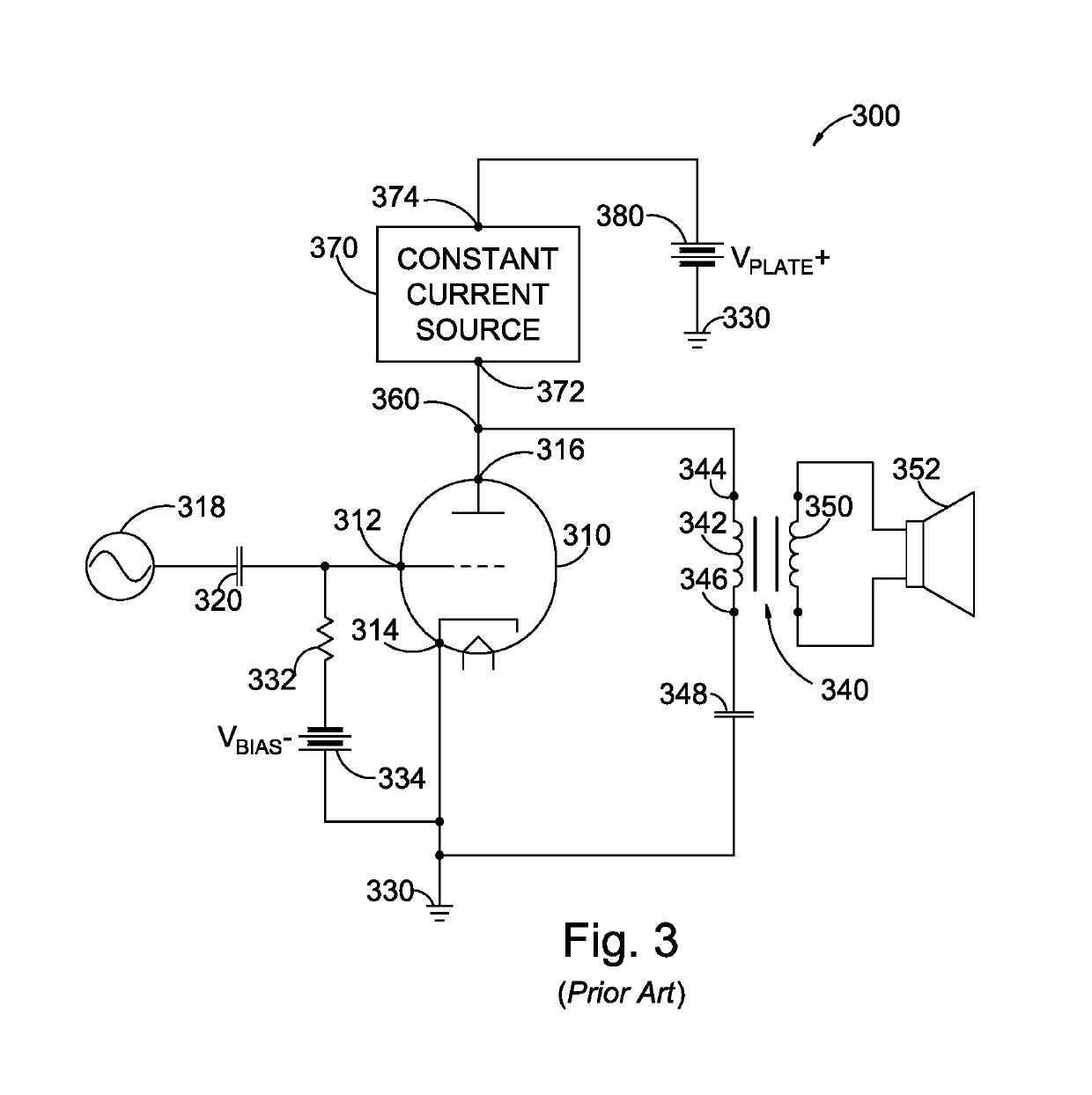
[0055]Reference will now be made in detail to embodiments of the present disclosure, one or more drawings of which are set forth herein. Each drawing is provided by way of explanation of the present disclosure and is not a limitation. It will be apparent to those skilled in the art that various modifications and variations can be made to the teachings of the present disclosure without departing from the scope of the disclosure. For instance, features illustrated or described as part of one embodiment can be used with another embodiment to yield a still further embodiment.

[0056]It is intended that the present disclosure covers such modifications and variations as come within the scope of the appended claims and their equivalents. Other objects, features, and aspects of the present disclosure are disclosed in the following detailed description. It is to be understood by one of ordinary skill in the art that the present discussion is a description of exemplary embodiments only and is n...


PUM


Abstract

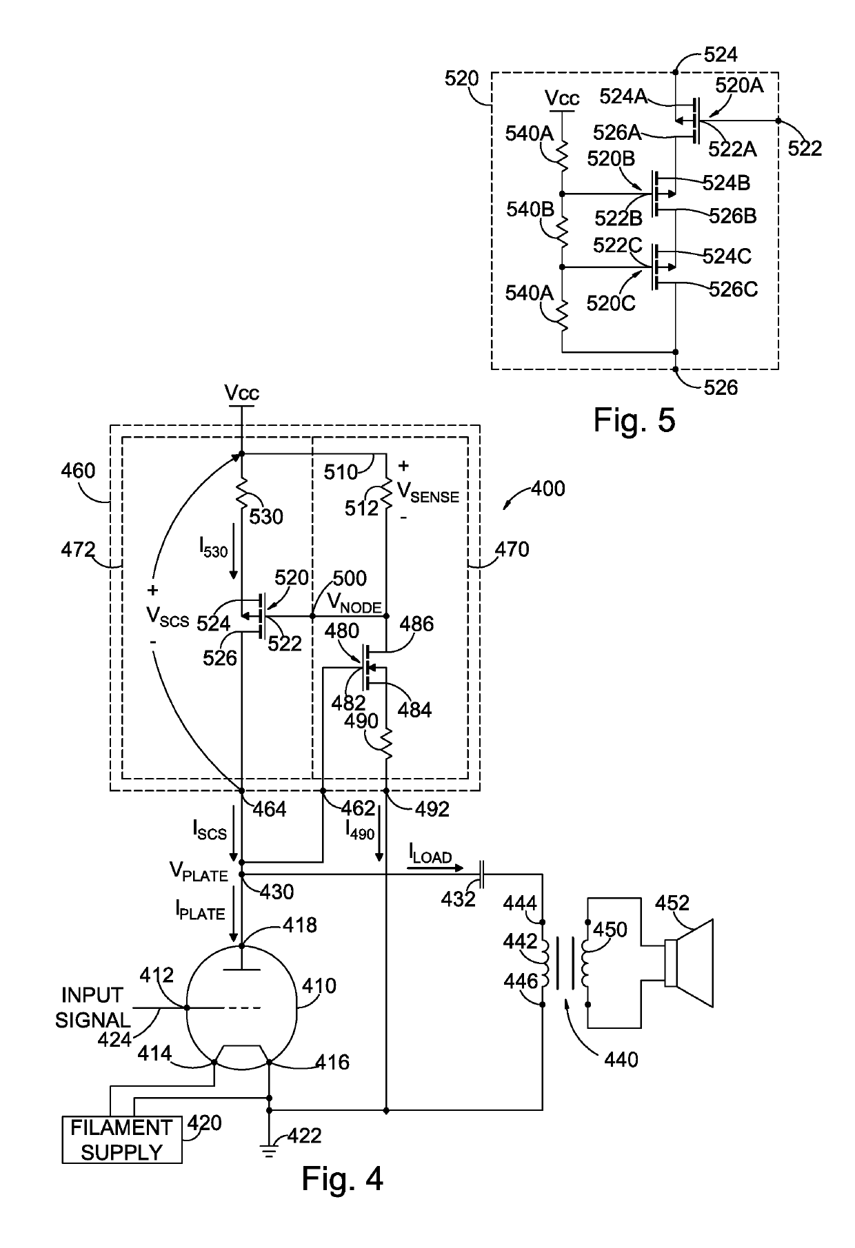
A single-ended Class-A amplifier includes an amplification component (e.g., a vacuum tube) having at least an output terminal, a reference terminal and a control terminal. The control terminal receives a time-varying input signal. The amplification component responds to the time-varying input signal to vary an output voltage on the output terminal and to vary a current flowing between the output terminal and the reference terminal. A load is AC-coupled to the output terminal. A steered current source has a voltage input coupled to the output terminal and has a steered current output coupled to the output terminal. The steered current source is configured to increase the steered current to provide current to the load when the output voltage on the output terminal of the amplification component increases and to decrease the steered current when the output voltage on the output terminal of the amplification component decreases.

Description

FIELD OF THE INVENTION[0001]The present disclosure relates generally to audio amplifiers, and, more particularly, relates to Class A audio amplifiers having a single amplifying element to drive a load.BACKGROUND[0002]For decades, vacuum tubes were incorporated into almost every aspect of electronic equipment, including audio amplifiers. With the advent of transistors followed by integrated circuits, vacuum tubes fell into disuse such that few, if any, modern televisions, radios, and similar electronic devices use vacuum tubes. However, a substantial group of “true” audiophiles consider the sound quality and performance of transistors and integrated circuits in audio equipment (e.g., stereo amplifiers) to be unsatisfactory because the sound from such modern amplifies tends to be cold and sterile. An increasing niche market exists for audio amplifiers having vacuum tubes in the power output stages.[0003]Two major methods of power stage operation are used to implement vacuum tube ampli...

Claims


Application Information

Patent Timeline
Patent Type & Authority Patents(United States)
IPC IPC(8): H03F1/04H03F3/30H04R3/00H03F3/181
CPCH03F3/181H03F3/30H04R3/00H03F1/04H03F2200/03H03F2200/541H03F1/0272H03F3/34H03F5/00H03F2200/462
Inventor MANIA, GUENTHERWHITENER, JR., CHARLES GEORGE
Owner WESTERN ELECTRIC EXPORT CORP
Why Eureka
Try Eureka