
Method for automatic positioning of lamps in a greenhouse environment

a technology of automatic positioning and greenhouse environment, which is applied in the direction of computer control, program control, instruments, etc., can solve the problems of cumbersome and time-consuming tracking, and achieve the effect of accurate determination of the position of light-emitting devices

Active Publication Date: 2019-04-16
HELIOSPECTRA
View PDF6 Cites 13 Cited by
  • Summary
  • Abstract
  • Description
  • Claims
  • Application Information

AI Technical Summary

Benefits of technology

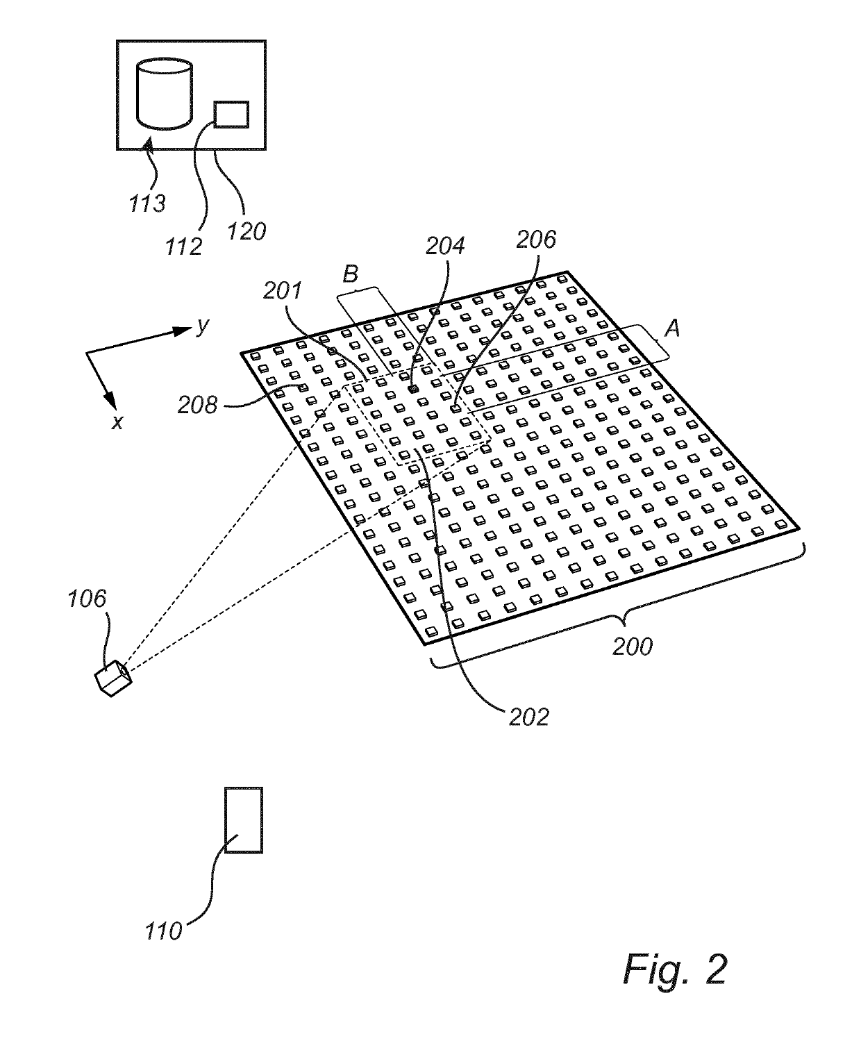
[0021]According to one embodiment of the invention, the set reference may comprise positions of at least two light-emitting devices of the set of light-emitting devices. By allowing two positions of light-emitting devices to be a set reference a more accurate determination of the positions of the further light-emitting device is possible. For example, an unintended movement of the camera device may more accurately be compensated for when two or more reference positions have been established in the grid. The positions of the set reference may be relative positions. In one embodiment of the invention, the set of reference positions may comprise relative positions of four light-emitting devices.
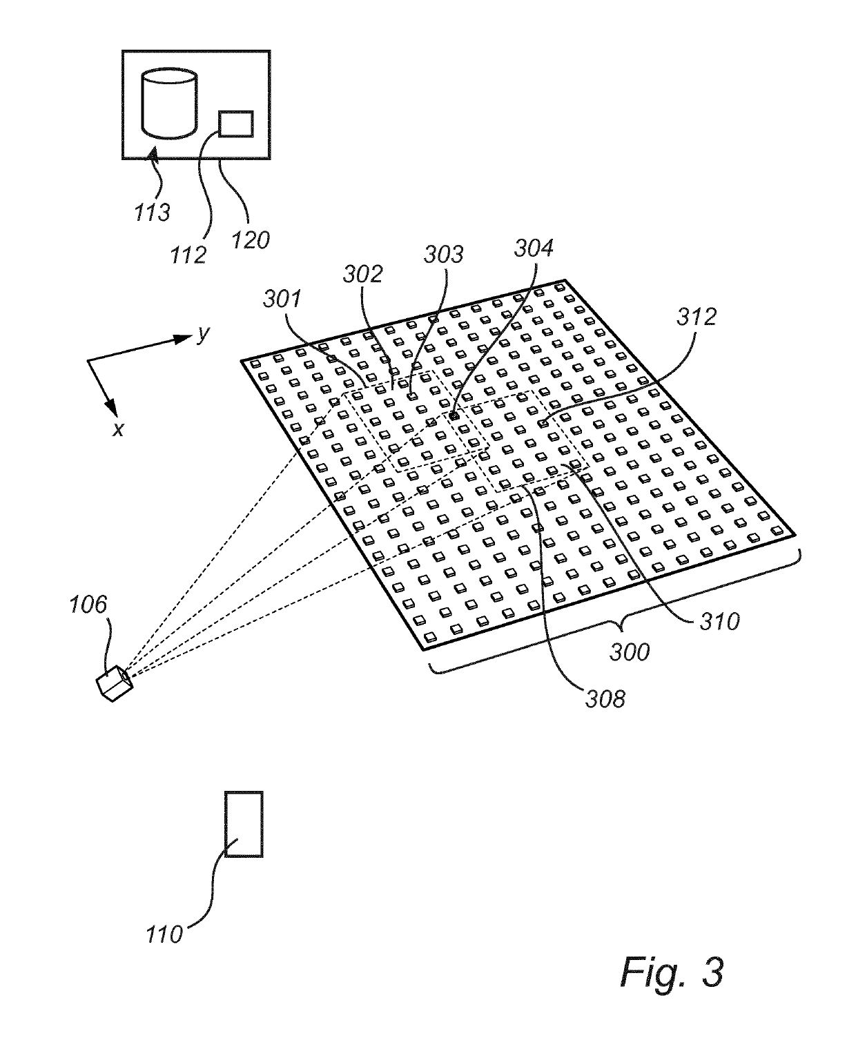
[0024]According to one embodiment of the invention, the method may comprise: acquiring further image data relating to a further camera view of a further set of light-emitting devices comprising at least one light-emitting device having a previously determined relative position, controlling a light-emitting device in the further set to emit light having a distinguishable property, wherein a relative position of the light-emitting device in the further set is determined relative the previously determined relative position. Thus, the camera device is moved from a first position to a second positions such that a further camera view is captured, in other words a panning action is performed with the camera device. The light-emitting device having a previously determined relative position may be considered to be part of a set reference when determining the relative locations of the light-emitting devices in the further set of light-emitting devices. Being able to move the camera such that it captures a further set of light-emitting devices and proceed with determining the locations of the light-emitting devices of the further set is advantageous for example when more than one camera view is necessary in order to capture all the light-emitting devices which positions are desired.
[0026]The steps for determining the outer boundary may be repeated for all light-emitting devices in the grid. In this way, the outer boundary is advantageously found in an efficient manner.
[0028]According to one embodiment of the invention, the method may comprise determining a location of the camera device relative the grid arrangement. For example, it may be advantageous to know from which direction (e.g. “north”, “south”, “east”, “west”, etc) the camera view is obtained. In this way, a more accurate determination of the positions of the light-emitting devices relative e.g. the interior of a building where the light-emitting devices are arranged may be obtained. For example, if the camera device is a hand-held device such as e.g. a camera device integrated in a mobile phone (e.g. a smart phone) a location of the camera device may be obtained directly from the mobile phone, either automatically if requested by a running algorithm or manually transmitted if needed at a later stage. Thereby, the direction (e.g. “north”, “south”, “east”, “west”, etc) from which the camera view is / was obtained may be determined.

Problems solved by technology

Using metal halide based lighting typically promotes shorter, bushy growth; whereas high pressure sodium based lighting in comparison typically tend to produce taller and stretched plants.
During installation of the light-emitting devices, it is cumbersome and time-consuming to keep track of which light-emitting device is mounted at what position in a grid of light-emitting devices.

Method used


Image

  • Method for automatic positioning of lamps in a greenhouse environment
  • Method for automatic positioning of lamps in a greenhouse environment
  • Method for automatic positioning of lamps in a greenhouse environment

Examples


Embodiment Construction

[0050]The present invention will now be described more fully hereinafter with reference to the accompanying drawings, in which currently preferred embodiments of the invention are shown. This invention may, however, be embodied in many different forms and should not be considered as limited to the embodiments set forth herein; rather, these embodiments are provided for thoroughness and completeness, and fully convey the scope of the invention to the skilled addressee. Like reference characters refer to like elements throughout.

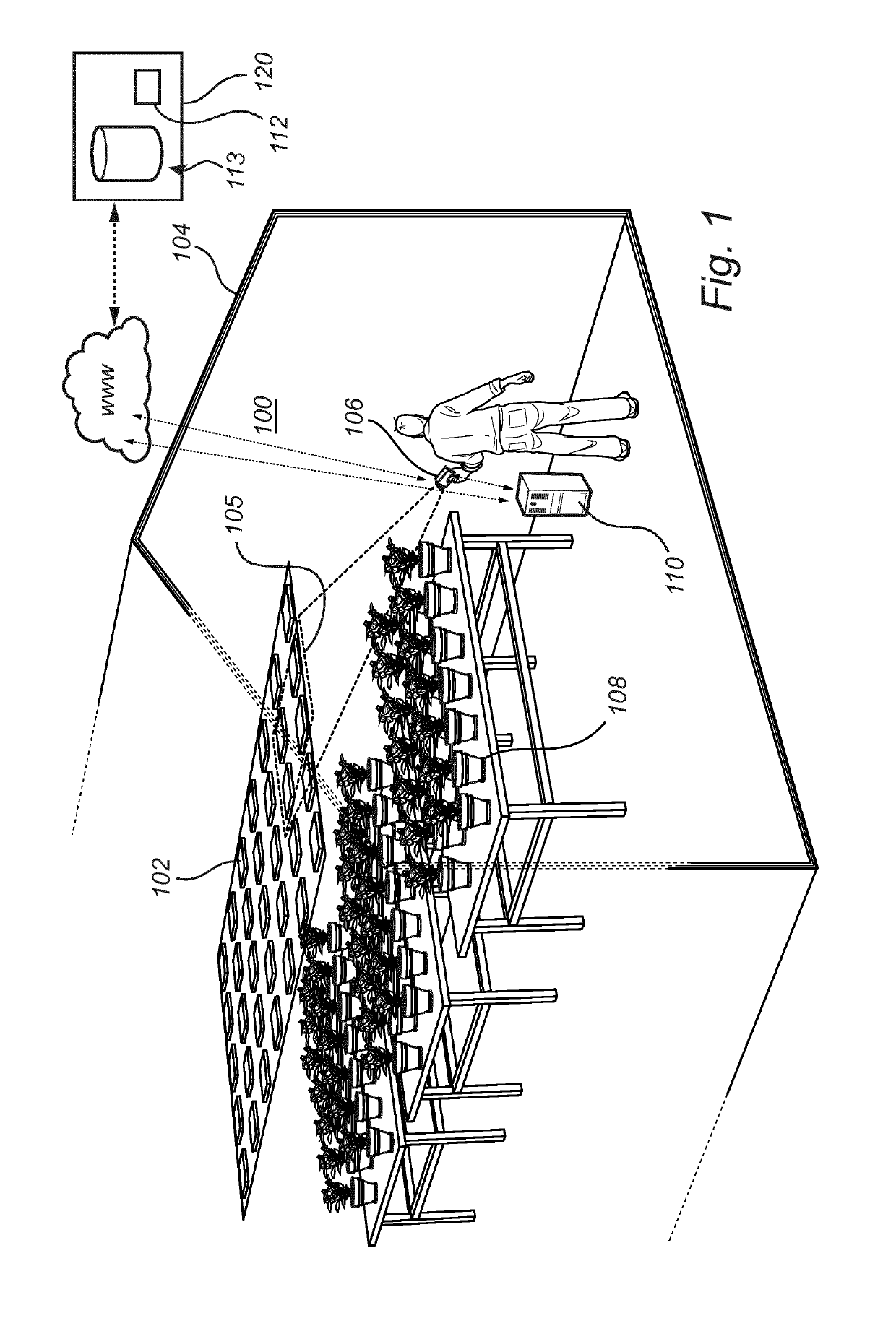
[0051]FIG. 1 shows an exemplary application for a system according to an embodiment of the invention. In FIG. 1 a system 100 for determining positions of a plurality of light-emitting devices 102 (only one is numbered in order to avoid cluttering in the drawing) is shown arranged in a controlled environment in the form of a greenhouse 104. Each of the light-emitting devices 102 is associated with a unique network address, for example a MAC-address, identifiabl...


PUM


Abstract

The present invention relates to a method for determining positions of a plurality of light-emitting devices arranged in a planar grid arrangement, each light-emitting device being individually controllable and having a unique network address. The invention also relates to a corresponding system and to a computer program product.

Description

TECHNICAL FIELD[0001]The present invention relates to a method for determining positions of a plurality of light-emitting devices arranged in a planar grid arrangement of an artificial light arrangement arranged to control growth of a plurality of plants in a controlled environment. The invention also relates to a corresponding system and computer program product.BACKGROUND OF THE INVENTION[0002]Artificial and supplemental lighting in e.g. a greenhouse typically involves use of an illumination system for stimulating plant growth, the illumination system comprising a plurality of high power light sources. Different types of light sources, having different light spectrum and providing different effects on growth stimulation, may be included, such as light sources based on metal halide (MH) or high intensity discharge (HID) which includes high pressure sodium (HPS). Using metal halide based lighting typically promotes shorter, bushy growth; whereas high pressure sodium based lighting i...

Claims


Application Information

Patent Timeline
Patent Type & Authority Patents(United States)
IPC IPC(8): H05B33/08G05B19/402G01B11/14A01G9/20H05B37/02G06T7/70G01B11/00G06K9/20H05B44/00G06V10/141
CPCG05B19/402A01G9/20G01B11/002G01B11/14H05B37/0245G06T7/70H05B33/0845H05B33/0857G06K9/2027H05B45/20H05B47/175H05B47/125Y02B20/40G06V10/141
Inventor HILLBERG, STAFFANCLENDINNING, KIRKGILLEY, ANTHONYPOHJANVOURI, TIMO
Owner HELIOSPECTRA
Learn More